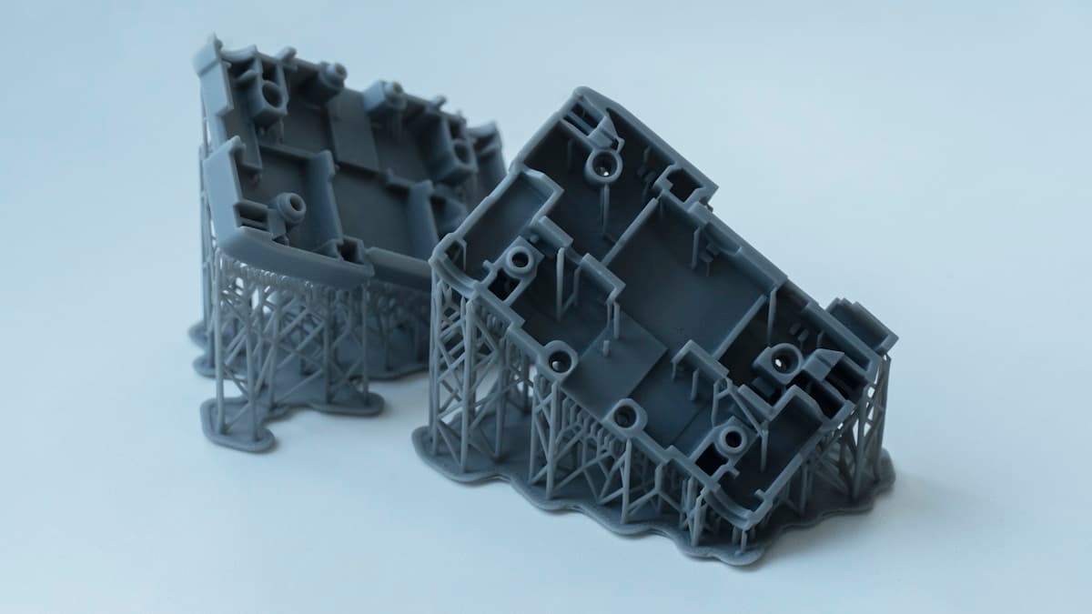
The surface finish is flawless, the detail is sharper than anything an extruder could manage, and the lid still will not go on. You measure it: the boss that should be 8.00mm reads 8.19mm, the 3mm pin hole takes a 2.8mm drill and nothing larger, and the long edge that measured right on a test cube is 0.4mm out across 120mm. Dimensional error on a resin printer is a different animal from the same complaint on an FDM machine — there is no flow rate to tune and no extrusion width to blame, because the part is formed by light rather than by a nozzle. It has five main causes, they produce different signatures, and the part in your hand tells you which one you have. When the tolerance is simply beyond a desktop machine, the provider directory is the honest end of the road.
This post contains affiliate links. If you purchase through these links, 3D Prototyping Hub may earn a small commission at no extra cost to you.
This post also contains Amazon affiliate links. As an Amazon Associate we earn from qualifying purchases.
Read the Error Before You Change a Number
Every cause below needs a different fix, and three of them get worse if you apply another one's remedy. Measure first, then match the signature.
| What you measured |
What it actually is |
Where to start |
| Outside dimensions large, holes small, by a similar amount |
Over-exposure — light bleeding past the pixel |
Exposure test |
| Everything undersize, thin features missing, supports snapping at the tip |
Under-exposure |
Exposure test |
| Error is a consistent percentage in X and Y, Z correct |
XY scaling — pixel pitch assumption |
Firmware scale compensation |
| Correct off the plate, smaller after the cure station |
Post-cure shrinkage |
Fix and record cure time |
| Soft, rounded, slightly undersize detail after a long soak |
Alcohol swelling during the wash |
Shorten and split the wash |
| First few millimetres flared, rest correct |
Bottom exposure over-curing the base |
Bottom layer settings |
The third row is the one people skip, because it looks like all the others until you compare a short feature with a long one.
Measure It Properly, or You Are Calibrating Noise
A resin part changes size while you are handling it, so the measurement protocol matters as much as the instrument.
Take every number from a part that has been washed, dried and fully cured, and that has come back to room temperature — a part measured warm out of the cure station reads large and shrinks while you write it down. Measure the same feature in three places and use the spread, not the best reading. And measure two features deliberately: something short, around 10mm, and something long, 100mm or more. A pair of digital calipers is the whole toolkit.
That pair of numbers splits the problem in half immediately. If the short and long features are both out by the same number of millimetres, the cause is a constant offset — exposure. If they are out by the same percentage, it is a scale error — shrinkage or pixel pitch. The same logic applies on the FDM side for completely different reasons, which is why dimensional error on an FDM machine reads as a separate article rather than this one with the words swapped.
Calibrate in an opaque material. Grey model resin gives you an edge you can actually see and measure to; clear and lightly pigmented resins scatter light deeper into the vat, which both enlarges the error and blurs the surface you are putting the calipers on. And wear nitrile gloves throughout — calibration means handling more green parts in an afternoon than normal printing does in a month, and uncured resin is a sensitiser whose effects accumulate.
Light Bleed Is Why Parts Come Out Bigger
This is the dominant cause, and it is worth understanding rather than treating as a number to nudge.
An MSLA printer images a whole layer at once by shining a 405nm array through an LCD mask. The mask defines where light should land — but light does not stop at the pixel boundary. It scatters at the edge, it passes through the pigment-thinned resin immediately beside the intended area, and the resin itself keeps reacting for a moment after the light stops. The result is a cured fringe a little wider than the pixel pattern that produced it, and the longer the exposure, the wider that fringe grows.
Every consequence follows from that one fact. Outside surfaces grow outward. Hole walls grow inward, so holes come out undersize. Narrow slots close up. Engraved text fills in. Sharp edges round over. And all of it by roughly the same absolute amount, regardless of how big the part is — which is exactly the signature in row one of the table.
Three things change how much bleed you get:
- Exposure time. The direct control. Print an exposure-test model and move in 0.2 to 0.5 second steps for a mono LCD. The direction of the error is readable: over-exposure gives oversize parts with closed holes and supports fused on hard, under-exposure gives undersize translucent parts with thin features missing and support tips snapping. The full reading of exposure symptoms is in why resin prints fail.
- Pigment and resin chemistry. An opaque grey stops light within a shorter distance than a clear or pastel resin, so it bleeds less and tolerates a wider exposure window. Changing bottles changes the correct exposure, which is the real argument for standardising: settling on one resin and buying it in a format like Chitu Systems' Conjure standard resin in 10kg means one calibration instead of one per bottle.
- Resin temperature. Reactivity rises with temperature, so the same exposure cures further on a warm evening than a cold one. A machine in an unheated room will drift seasonally, and the parts get smaller in winter. That is the same ambient-masquerading-as-settings problem described in why resin prints warp after curing.
Your slicer's anti-aliasing, blur and grey-level options interact with all of this, because they deliberately expose pixels at the part boundary at partial intensity. They improve the look of a curved surface and they also move your edges. Calibrate exposure with those settings at the values you intend to print with, not at defaults you will change afterwards.
Z Is Mechanical. X and Y Are Optical.
These two axes fail in completely different ways, and treating them as one system is why some calibrations never converge.
Z height comes from a lead screw turning a known number of steps per millimetre. It is a mechanical number, it is usually right, and when it is wrong it is wrong by a clean percentage across the whole height — a worn or badly fitted screw, a slipping coupler, or a firmware steps value that does not match the hardware.
X and Y come from the screen. In-plane resolution is the panel's pixel pitch, typically somewhere between 0.017 and 0.05mm, and the machine simply assumes the pixel is exactly the size the specification says. If the real pitch differs slightly, or if a replacement LCD is not quite the panel the firmware expects, every X and Y dimension is off by a fixed percentage while Z stays perfect. Most modern firmware exposes an XY scale compensation for precisely this, and the value is found by printing a large flat calibration part and dividing measured by nominal.
Two practical notes. Apply scale compensation only after exposure is correct, because it shifts everything by a percentage and will mask a constant offset badly. And treat the screen as the component that resets this calibration: a screen protector film is a few dollars against both the panel cost and the recalibration that follows a panel swap.
Shrinkage Happens Twice, and Only One Half Is Visible
Photopolymer shrinks as it cures, because the monomer molecules end up closer together than they started. Some of that happens on the plate during the print, and your part already carries it when you pull it off. The rest happens in the cure station.
Post-cure shrinkage is the one that catches people, because the part measured correctly before curing. It is proportional, so it barely registers on a 20mm test cube and is obvious across a 150mm panel, and it hits thin walls and small features hardest because they cure through to completion fastest. Over-curing also embrittles — a part cured for forty minutes "to be safe" is both smaller and more likely to crack during assembly.
The fix is procedural rather than clever. Measure a part green, then cure it for a recorded time and measure again. The difference is your post-cure shrinkage, and once you know it you can either design around it or apply it as a scale factor. What makes that number meaningful is a repeatable cure, which means a timed rotating cure station rather than a window sill and a guess; the practical options are compared in our wash and cure station guide.
The Wash Is a Dimensional Step, Not a Cleaning Step
Isopropyl alcohol swells partially cured resin. A short wash removes the uncured surface layer and does nothing else; a long soak penetrates, softens and lets fine detail round over, and the part does not fully recover when it dries.
Wash in two stages — dirty alcohol first to take the bulk off, clean alcohol second — and keep the total under about ten minutes. 99% isopropyl by the gallon is worth buying at volume for that reason alone: the main cause of long soaks is not having enough clean alcohol to run a second stage. An ultrasonic cleaner shortens the time further by doing mechanically what soaking does chemically. Dry the part completely before curing — trapped alcohol cures into a tacky film that reads as extra material on a caliper and is not, which is one of the ways a part that stays sticky after curing also measures wrong.
Holes, Pegs and Anything That Has to Mate
Once exposure and scale are right, the remaining error is design clearance, and it is cheaper to design for than to chase.
Holes will still come out tight, because bleed never goes to zero. Oversize them in CAD for the specific fit you need, and for anything taking a pin, a bearing or a fastener, print undersize deliberately and ream to size — the most repeatable option available on a desktop machine. Print a small test coupon carrying the actual mating features rather than a cube, because a 20mm cube tells you nothing about a 3mm peg in a 3mm hole.
Material choice matters at this point too. A press fit that is 0.05mm tight is absorbed by a tough ABS-like resin and splits the boss on a brittle standard resin, so the same dimensional error produces a working part in one material and a broken one in the other; the chemistries are compared in the resin buyer's guide. And if the printed part is a pattern rather than the finished article, the casting process adds its own shrinkage downstream — castable wax resin at least makes the burnout stage predictable, but a jewellery workflow needs the ring sized for the whole chain, not for the print.
When the Machine Itself Has Drifted
If accuracy was fine for months and has degraded gradually, look at hardware before settings.
A slack or clouded FEP film changes the geometry of each peel and how far the plate really travels before a layer forms, and it degrades continuously rather than failing outright — replacement film is a consumable, and the warning signs are in why resin vat film fails. An untrammed or loose build plate tilts the first layers and flares the base. Bottom exposure set too high over-cures the first few millimetres into a visible flare, which measures as a part that is oversize at one end only. And a tired LCD loses output unevenly across its area, so parts near one corner of the plate come out consistently different from parts in the middle — the same position-dependent error that shows up in horizontal lines and banding when the panel is the cause.
Machines differ in how much of this they hand you. Reading a specification sheet with accuracy in mind means looking at the stated XY pixel size rather than the headline layer height, at whether the Z axis is a single or dual linear rail, and at whether a replacement screen is sold for the model at all. ELEGOO's resin printer range and Anycubic's US store both list those figures alongside the vats, screens and cure equipment, which is also where the part numbers for a specific model are unambiguous; the broader comparison is in our resin printer round-up.
When the Tolerance Is Beyond the Machine
A calibrated desktop MSLA machine will hold roughly 0.05 to 0.1mm on small parts, and that number degrades with size as shrinkage accumulates over length. That is genuinely good — it is finer than any desktop extruder manages — and it is still not a specification you can promise a customer.
Three situations change the answer. A tolerance tighter than about 0.05mm. A part large enough that proportional shrinkage dominates. Or a batch that has to be repeatably in tolerance rather than in tolerance once, which is a harder problem than it sounds when resin temperature, screen age and cure time all drift. Industrial SLA and DLP machines address those by controlling the variables this article asks you to manage by hand — temperature-regulated vats, calibrated optics, documented cure cycles and an inspection report. The providers in our directory are listed by location and process, and the SLA versus FDM comparison covers which process to ask for before you ask for a price.
Work the order and most of this resolves in an evening: measure a short feature and a long one on a fully cured part, fix exposure until the constant offset disappears, apply XY scale compensation only afterwards, record a fixed cure time, and keep the wash under ten minutes. Everything left after that is design clearance, and clearance is something you control in CAD rather than negotiate with a printer. Handling practice through all of it is in resin safety and post-processing basics.
Hero photo by EnCata PD via Unsplash.