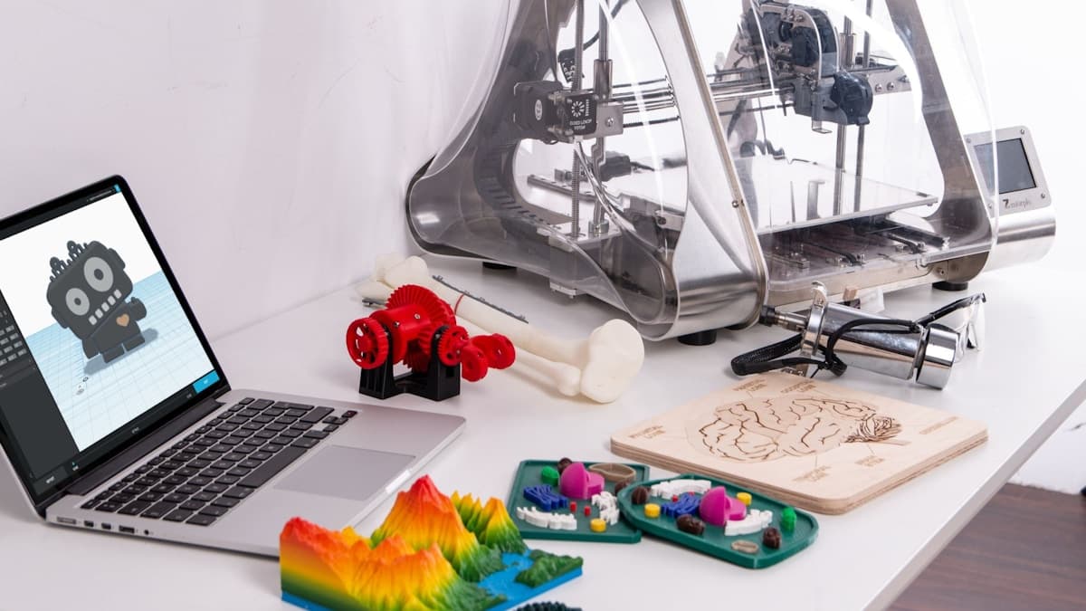
The clip that holds the dishwasher rack snapped, the part number is discontinued, and twenty minutes in CAD plus three hours on the printer produced something that looks exactly like the original. Two weeks later it is in two pieces again, in the same place. 3D printed replacement parts fail far more often than new printed designs do, and the reason is specific: you copied the shape of an injection-moulded part without copying the thing that made it work.
This post contains affiliate links. If you purchase through these links, 3D Prototyping Hub may earn a small commission at no extra cost to you.
This post also contains Amazon affiliate links. As an Amazon Associate I earn from qualifying purchases.
Read the Break Before You Reprint
The failure surface tells you which of five problems you have, and they need different fixes.
| How your copy failed |
What it actually means |
Section |
| Snapped clean across, flat face, no stretch |
Load ran across the layers |
2 |
| Broke at the root of a tab, boss or rib |
Missing fillet the moulded part had |
3 |
| Softened, sagged or went out of shape |
Material cannot take the service temperature |
4 |
| Screw boss stripped or split on assembly |
Printed threads doing a moulded part's job |
5 |
| Fits nothing, or fits and rattles |
Dimensions taken off the broken fragment |
1 |
| Went brittle and crumbled after months outdoors |
UV, not load |
4 |
1. The Broken Part in Your Hand Is Lying to You
A part you are replacing has, by definition, been used. It is worn where it rubbed, creep-deformed where it was loaded, swollen if it absorbed water, and missing the piece that broke off. Measuring it gives you the dimensions of a failed object.
Take the numbers off the assembly instead. The shaft the part turns on, the slot it slides in, the bolt spacing in the panel it mounts to — those have not changed. Use the broken part for topology, for which face goes where and what shape goes roughly around what, and use calipers on the mating hardware for anything that has to fit.
Two practical habits:
- Measure the same feature three times at different angles and take the sensible value. A worn bore reads differently across every diameter, and the number you want is the one it had when new.
- Check the radii with a radius gauge, not by eye. Moulded parts are covered in fillets because sharp internal corners crack moulds and parts alike. Those fillets are structural, and CAD will not invent them for you.
Then expect your printed dimensions to miss anyway. Printed holes come out small for several compounding reasons, and a replacement part is nearly all holes and slots — the measured compensation value that fixes this once is covered in why 3D printed holes come out undersized, and the clearance side of the same problem in why 3D printed parts don't fit together.
2. The Original Was Moulded, and That Is a Different Object
This is the heart of it. An injection-moulded part is one continuous mass of polymer, cooled under pressure in a steel tool, with roughly the same strength whichever way you pull it. Your part is a stack of extruded beads welded to each other by residual heat, and the weld is weaker than the bead. Across the layers a printed part typically gives up 30-60% of its strength.
So the same geometry has a grain, and the grain has to run the right way. Work out where the load goes — the direction the clip is sprung, the axis the lever is pushed on — and orient the part so that load travels along the layers rather than trying to peel them apart. Where a part is loaded two ways at once and no orientation serves both, split it into two printed pieces joined by a screw, which is a legitimate design rather than a compromise. The full treatment of grain direction is in why 3D prints snap along layer lines.
The other half of the difference is the polymer. Moulders use materials you cannot load into a desktop extruder: acetal (POM) for anything that slides, polypropylene for anything that flexes a thousand times, glass-filled nylon anywhere hot or stiff. Look on a hidden face for the moulded-in code between chevrons — >POM<, >PP<, >PA66-GF30<. It tells you what the designer thought the part had to survive, which is the brief you are now working to.
3. The Features That Look Decorative Are Not
A moulded part carries detail that exists for manufacturing reasons and ends up doing structural work. Copy the shape without them and you remove the strength along with the texture.
- Fillets at every root. The radius where a tab meets a wall spreads stress over an arc instead of concentrating it at a line. A 1mm fillet at the base of a clip is frequently the whole difference between a part that lives and one that snaps there every time.
- Ribs instead of thickness. Moulders cannot make thick sections — they sink and warp — so they stiffen a thin wall with ribs. Ribs work even better in printing, where they run as solid perimeters, and they cost almost nothing in time.
- Draft angles. Harmless to copy, and they tell you which way the part came out of the tool, which in turn tells you where the load-bearing faces are.
And do not reach for infill. Stiffness and bending strength in a printed part live in the perimeters and the solid top and bottom skins; past roughly 40% the lattice adds grams and hours rather than load capacity. Two extra walls beat twenty points of infill on almost every replacement part, for the reasons set out in why more infill doesn't make 3D prints stronger.
4. Match the Material to What the Part Has to Survive
The original failed after years in its environment. Yours starts there on day one, so the service conditions matter more than peak tensile numbers on a spec sheet.
| Where the part lives |
Sensible filament |
The honest limit |
| Indoors, light load, no heat |
PLA |
Softens around 55°C; brittle under impact and vibration |
| Household, warm, knocked about |
PETG |
Good to about 70-75°C; creeps slowly under sustained load |
| Outdoors, in sun |
ASA |
Needs an enclosure to print without warping |
| Sliding, geared, repeatedly impacted |
Nylon |
Absorbs water within hours; must be dried and kept dry |
| Hot and stiff, under a bonnet or near a motor |
PA-CF or PC |
Hardened nozzle, high temperatures, enclosed chamber |
| Flexing, sealing, damping |
TPU |
Slow to print; not a substitute for a moulded rubber seal |
Two environments deserve naming because they catch people out. A car interior reaches 60-80°C on a summer afternoon, which is above PLA's softening point and inside PETG's margin — the mechanism is in why 3D prints deform in a hot car. And sunlight destroys most filaments by chain scission long before weather does anything visible, which is why garden and vehicle-exterior parts want ASA; the evidence is in why 3D printed parts fail outdoors.
Dry the spool before anything structural. Nylon, PC and PETG all take up atmospheric moisture, and a damp spool makes a part that is weak before it is ever loaded — a dryer box is the cheapest strength upgrade in this whole article.
5. Put Metal Where the Plastic Cannot Win
A moulded boss takes a self-tapping screw a dozen times because the plastic around it is continuous. A printed boss has layer boundaries running across the thread, and it strips or splits on the second assembly.
Fit a heat-set brass insert and the thread is metal; the plastic only has to hold the insert, which it does well because the knurls load it over a long area. Where a part takes real load, pass an M4 screw and nut right through with washers both sides — now steel carries the tension and the plastic is in compression, which is the loading it is actually good at. The comparison between inserts, tapped holes and captive nuts is laid out in why 3D printed threads strip.
The same logic applies to wear. A printed gear running against a steel pinion wears out on a schedule you can predict (why 3D printed gears wear out); a printed carrier holding a steel bushing does not. Replace the moulded part's function, and let metal do the parts of it that were always metal-shaped.
What the Machine Has to Be Able to Do
Most of the materials above are not available to every printer, and buying the spool before checking the machine is a common and expensive order of operations.
ASA, PC and nylon all need a nozzle beyond 250°C, a bed above 90°C, and a chamber that holds its own heat so the part does not delaminate as it cools. An open bed-slinger will produce a warped, weak part from all three, and no slicer profile fixes that. If the parts you keep needing are in that category, the machine is the constraint: Flashforge's enclosed CoreXY machines pair a high-temperature hotend with a chamber designed around it, and ELEGOO's FDM range and Anycubic's FDM machines and spares both cover the enclosed and all-metal end of the market as well as the hotend parts for an upgrade.
On an existing machine, two cheap changes open up most of the list: an all-metal hotend to get past the PTFE temperature ceiling, and a hardened steel nozzle before the first gram of any filled filament. Glass and carbon fill cut brass visibly oval inside a spool or two, and the symptom is dimensions drifting on parts you have already proven.
When Not to Print the Replacement at All
There is a line, and it is about consequence rather than difficulty. Do not print a part in a braking, steering, towing, lifting or climbing path. Do not print anything that retains mains voltage, seals gas or pressure, or holds a child in a seat or a pushchair. Do not print a structural bracket whose failure drops something onto a person. The part is cheap in all those cases; the failure is not, and a printed copy fails in a brittle, sudden way that gives no warning — the pattern described in why 3D printed parts crack under vibration.
The other line is economic. If you need forty of them, or the part has to hold a bearing seat to a few hundredths, a desktop machine is the wrong tool even when it is capable. A shop can print it in a production-grade material, machine the critical features, or mould it if the volume justifies a tool — the comparison is in CNC machining vs 3D printing and in our guide to functional and end-use 3D printed parts, and quotes by process and location come from the provider directory.
For everything below that line, the method is short: take the dimensions off the assembly, read the material code on the original, choose a filament for the environment rather than the spec sheet, orient the part so the load runs along the layers, put the fillets back, and let brass and steel do the threading. The replacement that lasts is the one that replaced the job, not the shape.
Hero photograph by Xiaole Tao on Unsplash.