The lid fits one way round and binds the other. The pin that should slide into the printed boss will not start. The bracket pair you printed in March goes together and the reprint from last night does not, from the same file. 3D printed parts don't fit together for reasons that are almost always systematic rather than random — your machine has a dimensional signature, that signature is repeatable, and the clearance you modelled was smaller than it. Fix it once and every assembly you design afterwards fits first time. If the fit has to be right across a batch or against a bought bearing, the provider directory lists shops whose processes hold tolerances desktop FDM does not.
This post contains affiliate links. If you purchase through these links, 3D Prototyping Hub may earn a small commission at no extra cost to you.
This post also contains Amazon affiliate links. As an Amazon Associate we earn from qualifying purchases.
Find Out Which Mis-Fit You Have
Five distinct problems get described as "it doesn't fit", and they do not share a fix. What the pair does when you push them together tells you which one you have.
| What happens |
What it actually is |
Where to start |
| Will not start, but slides once it does |
No lead-in chamfer on the leading edge |
Chamfer, not clearance |
| Tight everywhere, by a consistent amount |
Modelled clearance below your machine's signature |
Clearance ladder |
| Tight only at the bottom of the mating face |
First-layer flare on one or both parts |
Elephant-foot compensation |
| Tight in one spot, loose elsewhere |
Seam blob, stringing or a warped face |
Deburr the spot, not the part |
| Fitted before, does not now |
Material change, machine change or flow drift |
Measure a coupon |
The first and the third account for most of them, and both are free to fix. Neither is a tolerance problem, which is why people who go straight to the clearance number often end up with a sloppy assembly that still catches on assembly.
Your Machine Has a Signature, and It Repeats
A printed part is not the size the model says. It is the size the model says plus a stack of offsets your machine applies to everything it makes: extrusion width versus nozzle diameter, how hard the first layer is squashed, belt tension, how the slicer approximates curves. The useful thing about that stack is that it is consistent. The same machine with the same profile is wrong by the same amount on every part, which means it can be measured once and designed around forever.
Two effects dominate, and they point in opposite directions:
- External dimensions come out large. The nozzle lays a bead with rounded shoulders that sit slightly outside the nominal wall, and over-extrusion widens them further.
- Internal dimensions come out small. The same shoulders grow inward, the slicer's straight-line approximation of a circle falls inside the true curve, and unsupported first layers over a hole sag toward the middle.
So a boss and the pocket it goes into both move toward each other, and the pair loses roughly twice what either part alone measures off nominal. That is why a 0.1mm clearance that looks generous in CAD disappears completely in plastic. The full mechanism behind the sizes themselves is in why prints come out the wrong size; here the only thing that matters is the number.
Get the number by printing a clearance ladder: a plate with one pin and six pockets stepped 0.05mm apart from 0.05 to 0.35mm, printed in the material and orientation you actually use. Ten minutes of print time tells you which column is a press fit, which is a sliding fit and which is loose, on your machine. Digital calipers turn that from an impression into a figure you can put in your CAD defaults.
Clearance Is a Number You Choose, Not One You Hope For
Once you have the ladder, every fit becomes a decision rather than a surprise. These are reasonable starting points on a calibrated desktop machine, stated as the total gap for the pair:
| Fit |
Total clearance |
What it feels like |
| Interference / press |
0.00–0.05mm |
Needs a clamp or a mallet; assembles once |
| Light press |
0.10mm |
Pushes home by hand, stays put without glue |
| Close sliding (lid, cover, tray) |
0.20–0.30mm |
Goes together smoothly, no visible slop |
| Free running (hinge, shaft, moving joint) |
0.40–0.50mm |
Moves without binding when warm or dusty |
| Captive nut or insert pocket |
0.20mm on the flats |
Drops in, does not rattle |
Two rules go with that table. Clearance is for the pair, not for each part — a 0.3mm sliding fit means 0.15mm off each side if you split it, and a surprising number of too-loose assemblies are a clearance applied twice. And clearance does not scale with part size, but shrink does: a 0.3mm gap is generous on a 20mm boss and marginal across a 200mm lid, because the shrink error grows with the span while the gap does not.
Three Places the Error Actually Lives
Before adding clearance, check whether the interference is in a specific place rather than everywhere. Adding global clearance to fix a local defect is how assemblies end up rattling.
The bottom 0.5mm of the part. The first layer is pressed into the plate and spreads, so every vertical face flares outward at its base. On a part that drops into a pocket, that flare is the only thing touching. Every modern slicer has an elephant-foot compensation setting, and a 0.4–0.5mm chamfer on the bottom edge of the model fixes it permanently — see why prints have elephant foot for the full set of causes.
The seam. Each perimeter loop starts and stops somewhere, and the blob at that point can stand 0.1mm proud. Inside a bore or on a mating face, it is a single high spot that reads as a tight fit. Move the seam to a non-functional corner in the slicer, or cut it off in two seconds; the rest of the geometry was fine. The mechanism is in why prints have a visible seam line.
Stringing and blobs in internal corners. A pocket that measures correct but will not accept its part often has a bead of material in the corner radius where the nozzle travelled. Look in the corners with the part held to the light before you touch the model.
Chamfer First, Then Clearance
The single highest-value change to how printed assemblies go together is a lead-in chamfer, and it costs nothing.
A square-edged pin entering a square-edged hole has to be aligned within the clearance before it will start at all — which, at 0.2mm, is more precision than your hands apply. Put a 0.5mm × 45° chamfer on the end of the pin and a matching one on the mouth of the hole, and the pair self-aligns as it closes. Nothing about the fit has changed; it simply has a funnel now. Most parts that "won't fit" fit immediately once chamfered, and they stay tight where they are supposed to be tight.
On parts already printed, a hand deburring blade cuts the same chamfer on a printed edge in about five seconds, with no chatter and no flat spot.
Adjusting the Parts You Already Have
When a reprint costs more than the fix, take material off — but take it off deliberately.
Work on one part of the pair only, and pick the one that is simpler, smaller or not cosmetic. Removing a tenth from each of two parts gives you two parts that are each wrong for everything else they mate with.
Sanding sticks and needle files are the right tools for a flat mating face, because they stay flat. Abrasive held in your fingers follows the surface, dishes the middle and leaves the edges standing, which converts a tight fit into one that rocks. For a sliding fit that has to feel good, finish with wet/dry paper from 400 upward on a flat block.
Check the fit every few passes. Printed plastic goes from tight to sloppy fast once the outer perimeter is breached, and the perimeter is typically only 0.4mm thick. If the feature is a round hole, stop and ream it instead of abrading it — the reasoning, and why a twist drill is the wrong instrument, is in why printed parts crack when you drill them.
A Material Change Invalidates a Tuned Fit
The clearance you calibrated is specific to the material you calibrated it in, because the shrink is.
Published shrink figures for the common filaments differ by roughly a factor of four across the range — PLA is the lowest of the group, PETG sits above it, ABS and ASA higher again, and nylon the highest, with the added complication that nylon absorbs moisture in service and grows afterwards. The numbers themselves matter less than the consequence: reprinting one half of a mating pair in a different material moves the fit, and the longer the mating span the more it moves, because shrink is a percentage.
Practical version:
- Keep both halves of a pair in the same material unless you have run the ladder in both.
- Reprinting a tuned PLA assembly in PETG for toughness? Re-check the fit on the first one off the plate, not on the tenth.
- Going to ASA for outdoor use is the biggest jump of the three, and an unenclosed machine adds warp on top of shrink — which is a fit problem as well as an appearance one.
- Nylon assemblies want checking after a week in the room they live in, not on the day they come off the plate.
When the Machine Is the Variable
If fits transfer badly between two of your own machines, or drift week to week on one, the dimensional signature is not stable — and no clearance number survives that.
Three things govern whether a dimension repeats, and all three are worth reading on a spec sheet before you buy: a rigid frame and properly tensioned belts (backlash shows up as one axis being consistently wrong), an extruder that meters the same volume every time, and a stable thermal environment. The last one is the one people skip. An enclosure holds chamber temperature steady, and steady temperature means steady shrink across a large part, which is exactly what a large assembly depends on.
Judged on published specifications rather than a shootout we did not run: ELEGOO's FDM range and Anycubic's US store are where to read extruder type and frame construction on the mainstream machines, and both are the unambiguous source for the belts, pulleys and wheels that decide repeatability as they wear. QIDI's enclosed CoreXY machines run Klipper, which exposes flow and motion calibration as parameters with built-in routines — the enclosure and the calibration are the two specifications that bear directly on whether a fit repeats.
None of that is necessary to make good assemblies. It is what you read if the diagnosis has already landed on the machine.
Design So the Fit Does Not Have to Be Perfect
The assemblies that always go together are the ones that do not depend on a number being exactly right.
- Chamfer every lead-in. Covered above, and worth repeating because it is free.
- Slots instead of round holes wherever two or more fasteners share a pattern. One round locating hole plus slots for the rest absorbs the position error that no amount of sizing fixes.
- Build in compliance. A split boss, a short flexure tab or a thin relief groove behind a mating face lets the plastic give by a tenth instead of refusing. This is how snap fits survive tolerance variation, and the same geometry that helps here is what stops snap-fit clips breaking.
- Locate on features, not on outlines. Two small bosses into two pockets register a pair far more reliably than two nominally identical perimeters.
- Print mating pairs together, same plate, same orientation, same spool. They then share an error rather than stacking two different ones.
- Let a fastener do the alignment where you can. A threaded insert and a screw pull two parts into position; a press fit asks the print to hold it.
Do It In This Order
- Hold the parts to the light and find where they touch. Local or global?
- Local: deburr the seam, the corner bead or the first-layer flare. Stop there.
- Global: measure both parts with calipers and compare to the model. Note which direction each is off.
- Print a clearance ladder in your material if you have not got your machine's number yet.
- Set the clearance in CAD, add chamfers to both halves, and reprint the cheaper part.
- Only then consider flow calibration, hole compensation or elephant-foot compensation in the slicer.
- Record the number that worked. It applies to every assembly you design on that machine.
When to Stop Adjusting and Buy the Fit
Three cases are not worth another evening.
Batch repeatability is the clearest: hand-fitting one assembly is a pleasant hour and hand-fitting twenty is attrition, and desktop FDM does not hold a tenth across a batch the way an industrial process does. Mating to a bought component with a real tolerance — a bearing seat, a shaft, an O-ring groove — is the second, because the tolerance belongs to the bearing and it is not negotiating. Position accuracy is the third: sizing a hole is easy, moving it is not, and the distance between two hole centres is set by shrink and by the machine rather than by any amount of finishing.
What to ask for, and how to put a tolerance on a quote instead of hoping, is in tolerances and accuracy in 3D printing. For the parts themselves, our provider directory lists shops by location and process — SLS, MJF, resin and machining all hold tighter and more repeatable fits than a desktop machine, and a quote on an uploaded file costs nothing to find out.
Everything else is three habits: measure the pair, chamfer the lead-in, and design the clearance instead of hoping for it.
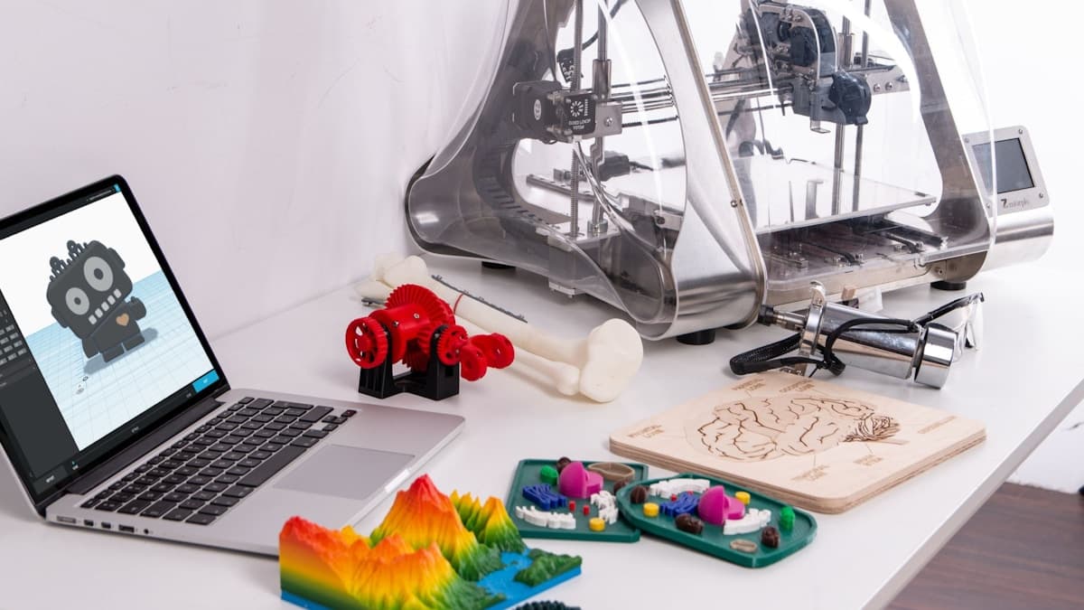
Hero photo by Xiaole Tao via Unsplash.