The gear meshed perfectly on the bench, ran for an afternoon, and now the mechanism slips under load. Pull it apart and the tooth flanks are glazed and rounded, there is a fine plastic dust in the bottom of the housing, and the teeth measure smaller than they did. 3D printed gears wear out faster than almost any other functional printed part, and the reason is that a gear is the one part where two printed surfaces rub against each other under load — a duty nothing about desktop FDM is naturally good at. The failures are readable, though, and most of them are decided before the print starts, in the material and the slicer rather than in the machine.
This post contains affiliate links. If you purchase through these links, 3D Prototyping Hub may earn a small commission at no extra cost to you.
This post also contains Amazon affiliate links. As an Amazon Associate we earn from qualifying purchases.
Read The Wear Before You Reprint
Four failure modes cover nearly every worn printed gear, and they do not share a fix. Match yours first.
| What you find |
What it actually is |
Where to start |
| Flanks glazed, rounded, plastic dust in the housing |
Abrasive wear plus friction heat |
Material and lubrication |
| Teeth bent or leaning, profile deformed but intact |
Creep — the material softened under sustained load |
Material heat resistance |
| Teeth snapped cleanly off at the root |
Layer bonds loaded the wrong way |
Print orientation |
| Pair binds, chatters, or one tooth in six skips |
Dimensional error, not wear at all |
Measure and compensate |
The last row is the one people misdiagnose most often. A pair that binds from the first minute was never the right size, and running it in only turns a fitting problem into a wear problem.
Heat Is The Killer, And PLA Is Where It Starts
Two plastic teeth sliding against each other generate heat at the contact, and plastic is a poor conductor — so that heat stays in a thin surface layer instead of spreading into the part. In metal gears the bulk carries it away. In a printed gear it accumulates exactly where the material is weakest.
That is why PLA gears fail so consistently despite PLA's respectable tensile numbers. It begins to soften around 60°C, and it creeps: held under load at room temperature, it slowly deforms and does not come back. A PLA gear does not need an oven to fail — the contact patch reaches its softening range on its own, the teeth round over, backlash grows, and the pair starts skipping. The stiffness that makes PLA feel strong in your hand is measured over seconds, and a gear is a load applied for hours.
The practical consequence: heat resistance and toughness matter more than tensile strength when choosing a gear material. A material that yields slightly and recovers outlives one that is stiffer and then shatters.
Most Printed Gear Teeth Are Hollow
Slice a gear and look at the preview in cross-section before printing it. On a 0.4mm nozzle at three perimeters, the walls take up roughly 1.2mm from each face — so any tooth thinner than about 2.4mm at its root has nothing but sparse infill in the middle, and at the tip it is often just two touching walls with a void behind them. It is an eggshell tooth, and it deforms under the first real load.
Three ways to fix it, in order of how much they help:
- Raise the wall count until the teeth are solid. Infill percentage barely touches a gear's teeth, because teeth are made of perimeters. Six or eight walls on a small gear is not excessive — check the preview, not the number.
- Use a bigger nozzle for bigger teeth. A 0.6mm nozzle fills a tooth profile in fewer, wider passes, which means fewer internal bond lines running down the tooth and a stiffer result. Hardened steel nozzles in 0.4mm and 0.6mm are the pairing to own, since the engineering materials below are abrasive enough to open a brass nozzle out of round.
- Increase the module. Fine teeth are a geometry the printer cannot describe. If the design permits, fewer, larger teeth on the same pitch diameter give the extruder something it can actually resolve, and they carry more load per tooth. Widening the face does the same job: double the face width and each tooth root sees roughly half the stress.
Orientation Decides Which Way The Teeth Break
Printed layers bond to each other more weakly than the material bonds within a layer — the property behind most functional print failures, and the one covered in detail in why prints snap along layer lines. On a gear, orientation decides which direction that weak plane faces.
Print gears flat, with the axis vertical. Each tooth is then built from continuous extrusions that wrap around the profile, and the bending load at the root runs along that material rather than across the bonds between layers.
Printed on its side, the same gear is a stack of discs glued face to face, and the tooth-root bending load pulls directly across the glue. Those teeth snap off whole, cleanly, often with no warning and no wear. If the geometry forces a vertical axis — a long worm, a tall helical gear — split the part and print the toothed section flat, or accept that you are now designing around the weakest orientation available.
Materials, By What The Gear Has To Do
Stated from material properties rather than a shootout we did not run:
| Material |
Realistic duty |
The catch |
| PLA |
Display, hand-cranked, prototype fit checks |
Creeps under load, softens near 60°C |
| PETG |
Light intermittent duty, low speed |
Not low-friction; do not run it against itself |
| ABS / ASA |
Warm environments, moderate load |
Needs an enclosure to print without splitting |
| Nylon (PA) |
Continuous running, real load |
Absorbs water fast; must be printed dry |
| Nylon + carbon fibre |
Load plus stiffness plus dimensional stability |
Abrasive; less forgiving at thin tooth roots |
| Acetal / POM |
The classic gear plastic |
Notoriously hard to get to stick to a bed |
For most people the useful ladder is short. PETG is the cheap step off PLA and is enough for a knob, a hand-driven mechanism or a low-speed drive that runs occasionally. Past that, the answer is nylon: it is what machined gears have been cut from for decades, it tolerates rubbing contact, and it fatigues gracefully instead of cracking. Carbon-filled nylon (PA-CF) adds the stiffness and dimensional stability that keeps a tooth profile true — at the cost of some toughness, so on very fine teeth plain nylon can outlast it. The full range and the trade-offs between grades are in our nylon filament guide.
One pairing rule worth more than any material choice: run dissimilar materials against each other. Two identical plastics in sliding contact tend to gall and pick up material from one another. Nylon against acetal, or a printed nylon gear against a metal pinion, wears far better than nylon on nylon.
Nylon Asks For Things Your Printer May Not Have
This is the step where gear projects stall, so it is worth knowing the cost up front.
Nylon absorbs water out of ordinary room air within hours, and wet nylon prints with steam voids and a rough, foamed surface — through the tooth root, which is precisely where the load goes. A sealed box with desiccant is not enough for a long print. A heated dryer that feeds the machine while it prints is part of the process for this material, not an upgrade to it; our dry box comparison covers the difference between storage and active drying.
It also does not want to stick to a standard sheet, and then warps off it. A garolite G10 plate is the usual answer — nylon bonds to it well when hot and releases as it cools.
And it wants a warm, still chamber. An open frame in a draughty room gives you weak interlayer bonding at the exact plane a gear tooth relies on. A passive enclosure helps; a heated chamber makes it repeatable. QIDI's enclosed high-temperature machines are built around that — the Plus5 and Max4 are enclosed with an actively heated chamber specified at 65°C, so the chamber is a number you set rather than one the room gives you. If you are comparing that class of machine rather than diagnosing a worn gear, the enclosed printer guide covers the field.
Mesh And Backlash Are A Measuring Job
A printed gear is larger than the gear in your CAD file. Extrusion width, first-layer squish and a nozzle that has worn slightly oversize all add material to the outside of every tooth, and in a meshing pair both parts carry that error, so the two bind against each other while each looks perfect on its own.
Do not sand it out. Measure the printed outside diameter with digital calipers, compare it to the drawing, and put the difference back into the design: add profile clearance, open the centre distance, or set a negative horizontal-expansion value in the slicer after measuring a single test gear. That number belongs to your machine and nozzle, so it is worth writing down once — the general approach to this is in tolerances and accuracy in 3D printing.
Then lubricate. A thin film of PTFE grease on the flanks does two jobs, and the less obvious one matters more: it carries heat out of the contact. Keep to plastic-safe greases — PTFE or silicone — and avoid unidentified petroleum products and penetrating oils, some of which soften thermoplastics over weeks in a way that reads as wear.
When To Stop Printing The Gear
Three signals that another spool is the wrong purchase. The gear runs continuously rather than occasionally. It carries torque that matters, in a tool or a machine rather than a model. Or it has to be interchangeable with a part somebody else made, to a tolerance you were given rather than one you chose.
Any of those, and the layer-stepped, slightly porous flank that FDM produces is working against you from the first revolution. Two processes fix it properly: SLS nylon parts come out dense and effectively isotropic, with no weak plane at the tooth root and a surface that beds in rather than abrading; machined acetal or steel gears are cut to a specified tolerance and simply do not have the problem. Both are quotable as one-offs, which is the part people assume they are not — the providers in our directory run exactly these jobs, and for one small gear the quote is frequently less than the engineering filament the next attempt would need.
For everything else, the order of work is fixed: choose for heat resistance and toughness rather than tensile strength, make the teeth solid, print the gear flat, measure what actually came out, and give the contact somewhere to send its heat. That covers most of what people call wear — and where it does not, the gear had outgrown the process, which is a different decision and a cheaper one than another weekend. If the part you are replacing came out of a machine that is no longer supported, 3D printing replacement and spare parts covers how to get it made once, properly.
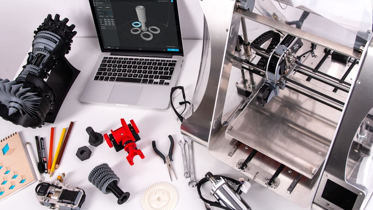
Hero photograph by ZMorph All-in-One 3D Printers via Unsplash.