The box you printed rocks on the table. The lid sits flush along one edge and stands a third of a millimetre proud at the opposite corner. A 200mm tower leans just enough that you keep turning it round to check. Nothing failed, nothing looks obviously wrong in the print, and the slicer preview was perfect — but the parts are out of square, and every assembly you build from them inherits it.
Crooked prints come from four separate faults, and they live in different places: the bed plane, the XY axes, the Z axis, and the part itself. They need opposite fixes, so the first job is not to adjust anything. It is to find out which one you have.
This post contains affiliate links. If you purchase through these links, 3D Prototyping Hub may earn a small commission at no extra cost to you.
This post also contains Amazon affiliate links. As an Amazon Associate I earn from qualifying purchases.
Read Which Kind of Crooked You Have
Six symptoms, four causes. Find yours in the left column before you touch a screw.
| What you see |
Where to measure |
What it is |
| Part rocks on a flat table, walls look straight |
Bottom face against a straight edge |
Bed or plate flatness |
| Rectangle's two diagonals differ |
Across the footprint with calipers |
XY skew |
| Tall part leans consistently in one direction |
Side of the part against a square |
Z not perpendicular |
| Lean gets worse with height, wavers in and out |
A tall thin tower |
Bent lead screw or binding Z |
| Base flares out for the first millimetre |
First 2mm of wall |
Elephant foot, not squareness |
| Everything is proportionally small or large |
Any known dimension |
Scale error, not squareness |
The last two rows are there because they get misdiagnosed as geometry faults more often than the real ones. A flared base and a part that is uniformly 0.4% undersized both leave a part that will not sit or fit, and neither is corrected by squaring anything.
Measure the Part Before You Measure the Machine
The part is easier to measure than the printer, and it carries the whole error in one number.
Print a flat square frame — 100mm on a side, 3mm tall, hollow in the middle so it has no large solid area to pull inward as it cools. Then take digital calipers to both diagonals, corner to corner.
On a square part those two numbers are identical. The difference between them is the skew, and it converts to an angle: a 0.3mm difference across a 141mm diagonal is about 0.12°. That is far too small to see and quite large enough to leave a 100mm lid sitting 0.2mm proud at one corner, which is exactly the complaint most people arrive with.
Do the same for the vertical. Print a tall thin tower — 150-200mm, 20mm square — and stand a machinist square against each face with the part on a flat surface. Height is what makes an angular error legible; a 20mm calibration cube will pass a check that a 200mm tower fails badly, because the same quarter-degree is 0.09mm on one and 0.87mm on the other.
Write both numbers down. Every fix below gets re-measured against them, because squaring a machine by feel usually moves the error somewhere else.
XY Skew Is the Frame, Not the Slicer
If the diagonals differ, the two horizontal axes are not meeting at 90°. On a Cartesian machine that is usually mechanical and usually boring:
- Frame bolts that were tightened out of square. Most kit and semi-kit printers are squared once, at assembly, on whatever surface it happened on. Shipping and two years of acceleration loosen that. Slacken the uprights, stand the machine on something flat, square it against the frame with a square, and retighten in a cross pattern.
- Belt tension that differs between axes or between halves of a CoreXY loop. A slack belt lets the carriage lag under acceleration, and the lag is directional — which prints as a parallelogram rather than as ringing. A GT2 tensioner makes that adjustment repeatable instead of a matter of thumb pressure.
- A loose carriage. Eccentric nuts backed off, a V-wheel worn flat, a rail screw loose. Grab the carriage and try to rock it: anything you can feel by hand is far more than the error you are chasing.
- A bed that moves. Clips in different positions, a plate seated on a crumb, a spring-steel sheet not sitting home on its magnet. This one re-appears after every print removal, which is a useful signature.
Skew that survives all four is usually constant, and constant errors are the ones software can cancel — see below. Skew that changes between prints is never a software problem.
A Leaning Tower Is a Z Problem
A lean that grows with height means the Z axis is not perpendicular to the bed, or is not travelling straight.
On a machine with two Z lead screws, the most common cause is the two sides sitting at different heights. Many open-frame designs let the gantry drop under its own weight when the steppers are disabled, and they drop unevenly, so the gantry is tilted before the print starts. The correction is mechanical: with power off, run the gantry down to the bed and let it rest there so both sides reference the same plane, or use the machine's own Z-align routine if it has one. If you want the number rather than the feel, a dial indicator on a magnetic base clamped to the carriage and swept from one lead screw to the other reads the difference directly.
The second cause is the Z lead screw fighting the guide rods. A screw that is slightly bent, or a coupler that is clamping the motor shaft off-axis, pushes the carriage sideways once per revolution — which shows as a lean that wavers in and out at a fixed pitch up the part rather than a clean tilt. That same mechanism produces Z banding, so a leaning tower with regular horizontal marks at the same spacing is one fault and not two.
The third is simply that the gantry is not square to the uprights, which is the vertical version of the frame problem above and has the same fix.
Bed Levelling Compensates the Base, Not the Geometry
This is the step that hides the fault, and it deserves its own paragraph.
A probe builds a mesh of bed heights and adjusts the nozzle during the first few layers so the first layer sticks everywhere. It does not change the direction the Z axis travels. So if the bed is physically tilted relative to the gantry, the mesh flattens the bottom of your part while everything above it is built perpendicular to the machine. The result measures square at the top, is sheared at the bottom, and sits unevenly — and the levelling report says the bed is fine.
The fix is to tram the bed mechanically first — a feeler gauge under the nozzle at four corners with the steppers off is enough to find a tilt — and leave the mesh to do what it is for, which is absorbing the millimetre-scale dishing of the plate itself. The wider version of that argument is in why auto bed levelling doesn't fix your first layer.
What Software Compensation Can and Cannot Do
Klipper's skew_correction, and the equivalent in some other firmware, measures a printed test piece and shears the toolpath to cancel a fixed angular error. Used after the mechanical work, it takes a good machine to a better one and is worth doing.
Used instead of the mechanical work, it fails for a specific reason: it can only cancel an error that is the same on every print. A loose bolt, a slack belt or a plate that seats differently each time produces a different error each time, and compensation calibrated against Tuesday's value makes Wednesday's print wrong in a new direction. Fix the mechanism, re-measure, then compensate the remainder.
The same ordering applies to dimensional corrections. Squareness and scale are independent: shrinkage factors and flow adjustments change how big a part is, never whether its corners are 90°. Both matter for assemblies, and the clearance side of that problem is covered in why 3D printed parts don't fit together.
When It Is the Part, Not the Printer
Three cases where a perfectly square printer still gives you a crooked part:
- Warping. Corners lift off the plate as the part cools, and a lifted corner is a geometry error you measure later. ABS and PETG do it on a scale that dwarfs machine skew — why 3D prints warp covers the fix order.
- Support-side sag. A face printed over supports sits a fraction low and is rarely flat. If the part must be square on a specific face, orient that face onto the plate.
- Layer shift mid-print. A single lost step offsets everything above it, so the part is square below the shift and square above it, with a step in between. That is a different fault with a different cause list: why 3D prints shift mid-print.
What the Hardware Genuinely Changes
Stated from construction and specification rather than from a shootout we did not run, three things decide how well a machine holds geometry over a tall part:
- The frame. A boxed or enclosed frame resists the twist that two uprights do not. QIDI's enclosed machines sit at that end of the market, where the structure holding the axes square is a box rather than an assembly you squared yourself.
- The motion system. Linear rails constrain the carriage in more directions than V-wheels on an extrusion, and they do not wear a flat spot that introduces play. ELEGOO's current printer range and Anycubic's current printer range both publish the motion specification per model — read it alongside whether dual Z is belt-synchronised or independently driven, because an independently driven pair is the one that needs aligning.
- Spares availability. A squaring repair two years in is only practical if the belt, pulley, lead screw or eccentric nut for your exact model is a stocked part. That is worth checking before you buy, not after.
None of that rescues a machine with a bent frame, and none of it is necessary if your parts are already within a tenth over 100mm.
When to Hand the Part Over
Squareness stops being a tuning exercise when it becomes the specification: a fixture that sets an angle, a housing that bolts to a flat plate, a mount whose alignment is the product. At that point you need a stated tolerance rather than a good result, and the honest limits of what any FDM process holds are in tolerances and accuracy in 3D printing.
A shop running tramming as routine maintenance — or machining the critical faces rather than printing them — delivers a part you can put a number on. Providers are listed by process and location in the provider directory, and sending one STEP file to two or three of them is usually quicker than a weekend of calibration prints.
The Order to Work Through
- Print the 100mm square frame and the 200mm tower. Measure the diagonals and the vertical. Write the numbers down.
- Rule out warping, support sag and a layer shift — those are part faults, not machine faults.
- Check the bed is mechanically trammed, not mesh-corrected into looking level.
- Rock the carriage and the bed by hand. Fix anything you can feel.
- Square the frame on a flat surface and retighten; check belt tension on both axes.
- Level the two Z lead screws, and check for a bent screw or an off-axis coupler.
- Reprint both test pieces and compare against step 1.
- Only now apply skew compensation to whatever constant error is left.
A crooked part is one of the few print faults that is almost never a slicer setting. It is the machine's geometry, written down at the resolution of your calipers — which also means that once you fix it, it stays fixed.
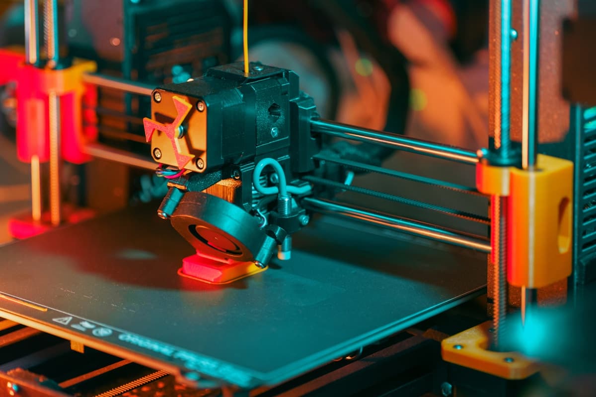
Hero image: a close view of an open-frame FDM printer's extruder carriage, X belt and Z lead screws above an empty steel bed. From the 3D Prototyping Hub image library.
Ready to find a 3D printing service provider?
Browse 2,000+ verified providers across the United States and submit your quote request free.
Browse Providers