The cube measures 20.00mm at the top and 20.31mm at the bottom. The bracket will not sit flat, the lid will not drop into its recess, and the bolt hole 2mm up from the base has gone oval. This is elephant's foot — a flare at the bottom of a print where the first layer or two spread out wider than the rest of the part — and it is the defect most likely to be dismissed as cosmetic right up until something has to fit.
The cause is not mysterious. The bottom of the part is squeezed between a nozzle and a plate while it is still soft, and soft plastic under load goes sideways. What varies is why it is still soft and how hard it is being squeezed, and those point at different fixes. Work down the table below in order, because the first entry is the answer roughly two times in three and the last two cost nothing.
This post contains affiliate links. If you purchase through these links, 3D Prototyping Hub may earn a small commission at no extra cost to you.
This post also contains Amazon affiliate links. As an Amazon Associate we earn from qualifying purchases.
Measure It Before You Change Anything
Print a 20mm calibration cube, let it cool completely, and take two measurements with digital calipers: the width across the very base, and the width 5mm up. The difference is your elephant's foot, and it tells you which section you are in.
| What you measure and see |
What it actually is |
Section |
| 0.15mm+ flare on every part, anywhere on the plate; first layer glassy and wide |
Z-offset too low |
1 |
| Flare plus visible ridges where first-layer lines piled into each other |
Over-extruded first layer |
2 |
| Flare only on tall or heavy parts, and worse the longer the print ran |
Bed too hot for too long |
3 |
| Flare in one region of the plate, clean elsewhere |
Plate not flat, or mesh is stale |
4 |
| Consistent 0.05–0.1mm you cannot tune away |
Normal squish — compensate or chamfer |
5, 6 |
The distinction that matters most is everywhere versus somewhere. A flare on every part regardless of position is a single number set wrong. A flare that depends on where the part sat is a geometry problem in the plate, and changing the Z-offset to fix it just moves the bad region.
1. The Z-Offset Is Too Low
This is the common one. If the nozzle sits closer to the plate than the commanded first-layer height, the plastic that will not fit in that gap has nowhere to go but out past the wall line. You get excellent adhesion and a flared base, which is exactly why it survives: the print succeeds, so nothing prompts you to look.
Fix it as a measurement rather than a feel. Raise the offset by 0.01–0.02mm, print the cube, measure base against 5mm up, repeat. You are looking for the highest offset that still produces a first layer with no gaps between adjacent lines — one step further and you are in why 3D prints don't stick to the bed territory, which is the same dial at the other end.
If your machine has no live-adjust and you level against the plate by hand, stop using paper. A sheet of copier paper is somewhere between 0.08mm and 0.12mm depending on the stock and how hard you pull it, and that spread is larger than the defect you are chasing. A feeler gauge set gives you a 0.05mm leaf that is 0.05mm every time, so the four corners actually match each other.
2. The First Layer Is Over-Extruded
Same symptom, different lever. If the flare comes with first-layer lines that are visibly piled against each other — ridged rather than smooth — you are pushing too much plastic into a gap that was already correct.
Three settings to check, in order:
- Initial layer flow. Many profiles ship this above 100% for adhesion. At 110% or 120% the excess has to escape somewhere, and the perimeter is the nearest exit.
- Initial layer height and width. A 0.2mm first layer at 0.6mm width is a lot of material to place at once. Dropping the initial layer width toward the nozzle diameter usually cleans the edge up immediately.
- Overall extrusion multiplier. If the whole part is slightly over-extruded, the base is just where it shows first. Print a single-wall cube, measure the wall, and correct the multiplier by the ratio — the same calibration described in why 3D prints are the wrong size.
3. The Bed Is Hot for Longer Than the Part Can Stand
A bed at the top of its range does not only help the first layer stick — it holds the bottom few millimetres of the part near its softening point for the entire print. Then the mass above presses down on warm plastic for six hours. The result is a flare that grows with part height and print time, which is the signature of this cause rather than the others.
PLA is the usual victim because 70°C is both a common default and uncomfortably close to where PLA goes soft. On a clean surface, 55–60°C holds perfectly well. Most slicers expose a separate first-layer bed temperature, and that is the right place to make the change: hot for the layer that needs to stick, cooler for the hundreds that need to hold their shape.
Do not take this too far on materials that need the heat. ABS, ASA and polycarbonate rely on a hot bed and a warm chamber to stay bonded at all, and starving them of it trades a flared base for a part that lifts at the corners — the failure covered in why 3D prints warp. For those, fix the flare with sections 1, 5 and 6 instead.
4. The Plate Is Not Flat
If the flare is regional — bad in the middle and clean at the edges, or bad along one side — no single Z-offset can be right everywhere, because the distance from nozzle to plate is genuinely different across the bed.
Run a fresh mesh first; a bed mesh stored six months and two plate swaps ago is describing a surface that no longer exists. Many machines also want the mesh taken at printing temperature, since an aluminium bed at 60°C is not the shape it was cold.
If a fresh mesh does not fix it, the plate itself is the problem. Spring steel sheets get dished by aggressive part removal and dented by scraping; glass gets chipped at the clips. A flat textured PEI spring steel sheet removes the variable outright, and it is worth having a spare anyway — our build plate guide covers which surface suits which material. On older machines that level on four springs, replacing them with silicone levelling columns stops the bed drifting out of level between prints, which is what makes a "fixed" flare come back a week later.
5. Elephant Foot Compensation, Used Honestly
Every serious slicer can shrink the first layer's outline inward to cancel the spread. PrusaSlicer and Orca call it elephant foot compensation; Cura calls it initial layer horizontal expansion and expects a negative number. The useful range is 0.1mm to 0.2mm.
Use it after sections 1 through 4, not instead of them. The setting does not stop the squish — it removes material from the layer that is being squished, so the flare lands back at nominal size. Set it to 0.5mm to paper over a badly low Z-offset and you have shrunk the contact patch holding the part to the plate, and you will lose a print to it eventually. Compensation is for the last 0.1mm that is simply what happens when a nozzle presses hot plastic onto a plate.
6. Chamfer the Base in CAD and Stop Thinking About It
For a part that has to mate with something, the permanent answer is geometry. Put a 0.5mm chamfer at 45 degrees around the bottom edge of the model. The flare then has somewhere to go that is still inside the part's envelope, the base self-locates instead of catching on the edge of a recess, and the fix travels with the file to any printer and any material.
This costs one CAD operation and is the reason mass-produced injection-moulded parts have a chamfer or radius at nearly every bottom edge. If you are designing parts that assemble, read it alongside tolerances and accuracy in 3D printing — the clearance you allow for a fit and the chamfer you put on the lead-in solve related problems, and designing both in is cheaper than trimming either out later.
Rescuing Parts You Have Already Printed
You do not need to reprint a batch over 0.2mm.
A deburring tool with a swivel blade is the fast option: run it around the bottom edge at about 45 degrees under light pressure and it cuts the lip away in one pass, leaving the chamfer you should have modelled. Most 3D printing tool kits include one alongside the flush cutters and the removal spatula.
Where the whole base must be flat — a part that has to sit without rocking — tape 240-grit paper to glass or a granite tile and move the part over it in figure-eights, keeping it flat with your fingertips spread. Do not sand the part freehand with a block: you will round the edges and end up with a base that rocks in a new direction. Finish at 400 grit if the face shows, and sanding sticks and needle files get into recesses the tile cannot reach.
When the Bottom Face Is the Product
There is a point where this stops being worth your time. If the base is a fit surface — a press-fit spigot, a flange, a part that slides into a track or locates on a pin — then a 0.2mm flare is a rejected part, and hand-finishing fifty of them costs more than having them made properly.
That defect cannot occur on SLA or powder-bed processes, because nothing presses the first layer against a plate: the part is built in a vat or a bed of powder with no mechanical squish at the bottom face at all. If you are printing functional parts where the base has to mate, the provider directory lists shops by location and process, so you can compare a resin or SLS quote against another weekend spent deburring.
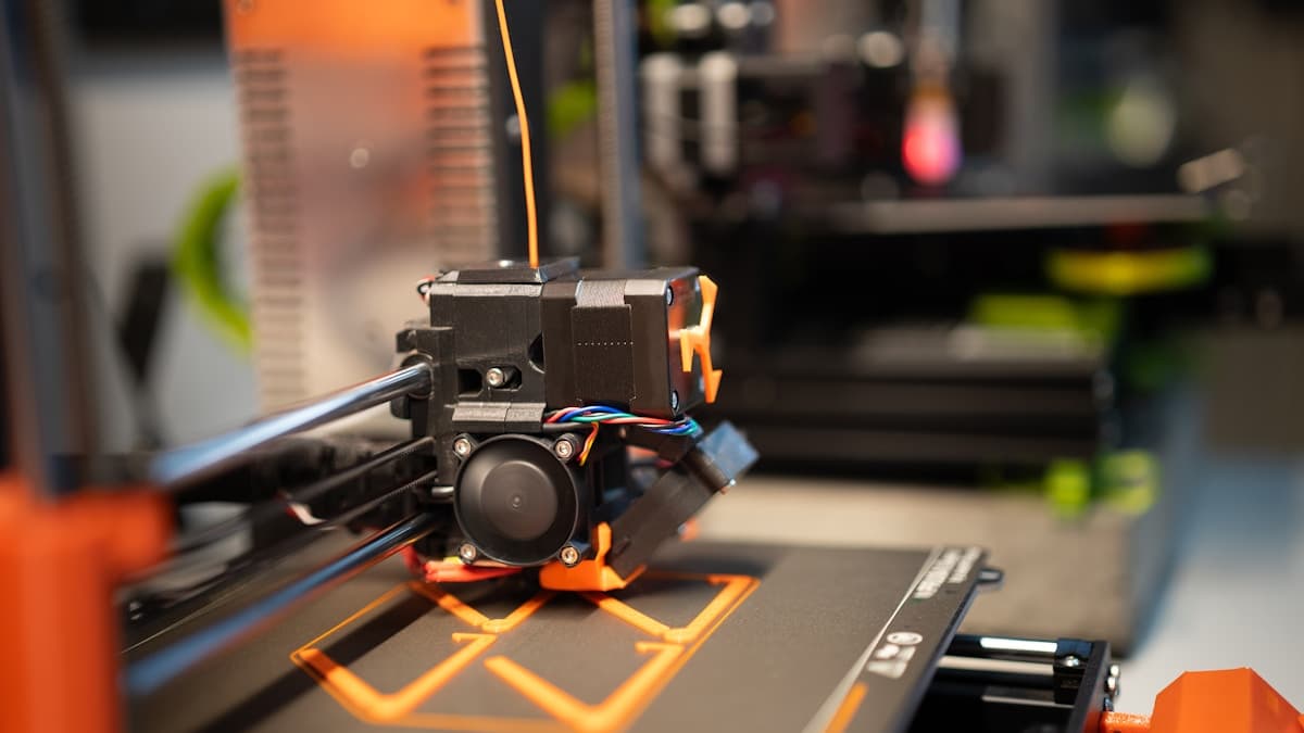
Hero photograph by Jakub Żerdzicki via Unsplash.
Ready to find a 3D printing service provider?
Browse 2,000+ verified providers across the United States and submit your quote request free.
Browse Providers