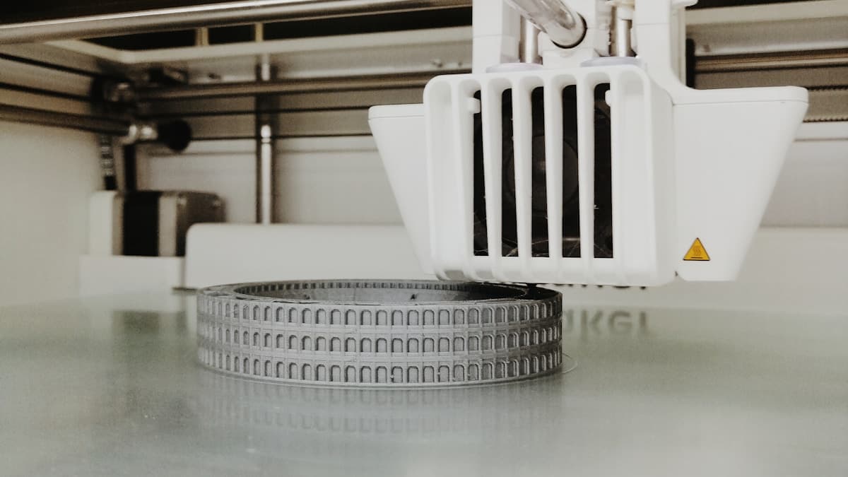
The part is dimensionally fine, the corners are sharp and nothing failed — but there are horizontal stripes running around it, and they catch the light from across the room. Z banding is the one surface defect people diagnose by staring at, which is why it takes so long to fix: four unrelated faults produce stripes, and the only thing that separates them is the vertical distance between one band and the next. Measure that first. Ten seconds with a pair of calipers puts you in the right section of this article, and every section below is a different machine.
This post contains affiliate links. If you purchase through these links, 3D Prototyping Hub may earn a small commission at no extra cost to you.
This post also contains Amazon affiliate links. As an Amazon Associate we earn from qualifying purchases.
Measure the Period Before You Touch Anything
Print a hollow test tower — a 25mm square or cylinder, 60mm tall, two walls, no top and no infill. It takes about twenty minutes and it removes infill, seams and cooling from the picture.
Then measure the distance between two bands with digital calipers, preferably across five bands divided by four rather than one gap, which averages out your reading. That number is the period, and it identifies the cause:
| Period between bands |
What it means |
Section |
| 8mm, or 4mm, or 2mm — matching your leadscrew lead |
Once per screw revolution: mechanical Z |
1 |
| Alternating thick/thin layers, period equals 2 layers |
Layer height is off the motor's full-step grid |
2 |
| No fixed spacing, irregular, changes up the part |
Extrusion volume is not constant |
3 |
| Regular but tied to time, not height |
Hotend temperature is oscillating |
4 |
One more check before you start: run a finger along a band. If the ripple appears after corners and fades along the wall, you are looking at ringing and ghosting, not banding. That is a vibration problem in X and Y and nothing in this article will help it.
1. The Z Axis Is Steering the Print Head
This is the classic, and the period gives it away completely: bands spaced at exactly one revolution of the leadscrew. A T8 screw with an 8mm lead gives 8mm bands. A 2mm-lead screw gives 2mm bands, fine enough to read as a texture rather than stripes.
The principle is that leadscrews lift, and rails locate. When the screw also ends up positioning the gantry, any runout in it — a slight bend, an off-centre coupler, a nut clamped rigid — is transferred into the X axis as a sideways wobble that repeats once per turn.
Work through it in this order, cheapest first:
- Clean and re-grease the screw. Old grease packed with dust and stray filament makes the nut bind intermittently. Wipe the screw down, then re-apply PTFE lead screw grease sparingly. This is a ten-minute job that resolves more cases than it has any right to.
- Check the coupler. The grub screws must land on the flat of the motor shaft, not the round, and the screw must not be bottomed out inside the coupler — it needs a millimetre of clearance so it can float. A stiff or seized flexible shaft coupler is one of the most common single causes of an 8mm band, and they do stiffen with age and heat.
- Loosen the nut mount. Undo the bolts holding the leadscrew nut to the gantry, run the axis up and down its full travel, and re-tighten at mid-height. On machines where the nut is hard-mounted, slotting the holes slightly so it can float sideways is a permanent fix. A sprung POM anti-backlash nut also removes the play that lets the gantry settle a different amount on every layer — but mount it so it can still move laterally, or you have simply bolted a better nut into the same bad geometry.
- Roll the screw on glass. Take it off and roll it across a flat surface. A visible gap under the middle means it is bent, and nothing else on this list will fix that.
Only after those: on V-slot machines, check the wheels carrying the gantry or the bed. A wheel that has gone loose, or has a flat spot from sitting in one place, lets the carriage rock a little on every layer. A fresh set of POM V-wheels with eccentric nuts adjusted to grip firmly but still turn by hand removes the variable.
2. The Layer Height Is Between Full Steps
Some banding is arithmetic, not hardware, and it is invisible until you know the number.
A 1.8-degree stepper makes 200 full steps per revolution. On an 8mm-lead screw, one full step moves the gantry 0.04mm. Microstepping subdivides those steps electrically, but the intermediate positions are not evenly spaced — a microstep holds position less accurately than a full step does. Ask for a layer height that never lands on a full-step boundary and each layer is placed with a slightly different error, which reads as alternating light and dark bands two layers apart.
So on that machine, use multiples of 0.04mm: 0.12, 0.16, 0.20, 0.24, 0.28. The conspicuous casualties are 0.15mm and 0.25mm, both of which are slicer defaults somewhere.
Check your own machine before adopting this, because it is not universal. Printers with a 2mm-lead screw have a 0.01mm full step, and every layer height anyone uses divides into that evenly. If switching from 0.15mm to 0.16mm makes no difference at all, that is the answer, and you should be in section 3.
3. The Flow Rate Is Not Constant
If the spacing is irregular — bands a few millimetres apart in one place and a centimetre apart elsewhere, sometimes fading entirely — the Z axis is fine and the problem is how much plastic arrives.
Measure the filament. Take ten caliper readings over a metre, rotating 90 degrees between each. Good material holds ±0.02mm; budget spools run ±0.05mm or worse. That matters more than it sounds, because flow goes with the square of the diameter: 1.80mm instead of 1.75mm is about 6% more plastic through the nozzle, on a surface where 6% is plainly visible. A spool with a diameter problem cannot be tuned out, and it is worth reading alongside why prints come out under-extruded — the same measurement underpins both.
Dry the spool. Moisture is the cause people skip because the filament looks fine. Absorbed water flashes to steam in the melt zone, the pressure in the nozzle fluctuates, and flow stops being constant — usually with a rougher surface and faint popping. PETG, nylon, TPU and PVA get there within days of opening a bag. A heated filament dryer at the material's recommended temperature for four to six hours is the test; if the banding changes, you have your answer without touching a single bolt.
Look for a partial blockage. A nozzle half-obstructed by carbonised material passes a variable amount of plastic depending on pressure and speed. If the banding arrived gradually over weeks, this is likely, and a cold pull with a nozzle cleaning kit costs nothing to try — the full diagnostic is in why 3D printer nozzles clog.
Check the grip on the filament. A worn drive gear, a tensioner set by guesswork, or a spool that binds and then releases all deliver plastic in surges. The spool is the one people miss: if the bands sit roughly half a metre apart, that is about one revolution of a half-full spool, and the filament is snagging on its own coil. A dual-drive extruder fixes the grip half of that on machines still running a single-sided gear.
4. The Hotend Temperature Is Oscillating
An untuned PID loop swings the nozzle a few degrees either side of the setpoint on a cycle of roughly thirty to sixty seconds. Viscosity follows temperature, flow follows viscosity, and you get bands at whatever height the machine reaches during one swing.
The tell is that the pattern follows time rather than geometry. Print your test tower again at half speed: mechanical causes stay at the same height, because 8mm is still one screw revolution. A thermal cause stretches, because each layer now takes twice as long and fewer layers fit inside one temperature cycle.
The fix is a PID autotune at the temperature you actually print at, with the part cooling fan running — tuning a cold hotend in still air produces values that do not hold in the middle of a print. Then deal with the draft: an open window or an air-conditioning vent blowing across the machine will defeat a well-tuned heater, and it is the reason a fault sometimes appears only in the evening.
The Ten-Minute Sequence
- Print the 60mm hollow tower.
- Measure five bands and divide by four.
- Matches the screw lead? Go to section 1 — grease, coupler, nut, straightness, in that order.
- Doesn't match, and the layer height is 0.15 or 0.25mm? Reprint at 0.16 or 0.24mm.
- Still banded? Reprint at half speed. If the spacing changed, it is thermal — autotune.
- If the spacing did not change and is irregular, it is flow — measure the filament, then dry it.
Change one thing between prints. The reason this defect has a reputation for being stubborn is that people arrive at it with four fixes at once and cannot tell which one worked, so it comes back and nobody knows why.
What to Do About the Print You Already Have
Banding is a surface artefact, so it sands out, and matte finishes hide it far better than gloss does — a matte filament and a textured plate will make a mild case invisible without touching the machine.
Be honest about when that is acceptable. A prop or an enclosure that will be painted: sand it, prime it, move on. A master for silicone moulding is different, because every band is reproduced in every copy cast from it. And if the banded surface is a sliding or sealing face, it is not cosmetic at all — the ridges are a dimensional deviation, which is the subject of our guide to tolerances and accuracy.
When the Finish Is the Product
There is a point at which chasing this stops paying. If the surface is what the customer is buying and the deadline is next week, the third diagnostic tower costs more than the part.
Neither SLA nor powder-bed processes have this failure mode: no leadscrew lifts a gantry between layers and no filament is pushed through a nozzle, so the two dominant causes above cannot occur. The provider directory lists shops by location and process, so you can price a resin or SLS quote against another weekend on the test tower and decide with a number rather than a feeling.
Hero photograph by Andrea G via Unsplash.