The scan came out beautifully. Every curve is there, the surface finish is visible, you can read the casting marks. Then you import it into Fusion or SolidWorks and the session hangs for two minutes, "convert to solid" greys itself out or fails, and when something finally appears you cannot put a sketch on it, cannot dimension the bore, cannot change anything. Nothing went wrong in the capture. You are trying to turn a 3D scan into a CAD model, and those are two different kinds of object: a scan is a surface made of triangles, and a CAD model is a set of features with intent behind them. This page covers how to read which problem you actually have, what to fix in the mesh before CAD ever sees it, and the point where the provider directory is the shorter route than another evening of retopology.
This post contains affiliate links. If you purchase through these links, 3D Prototyping Hub may earn a small commission at no extra cost to you.
This post also contains Amazon affiliate links. As an Amazon Associate we earn from qualifying purchases.
A Mesh Is Not a Model, and the Difference Is Intent
A scan is a shell of triangles. Two or five or ten million flat facets approximating a surface, each one a measurement with noise on it. There is no concept of a cylinder in that file — a bore is a few thousand facets that happen to sit near a cylindrical surface, each of them a tenth of a millimetre off in some direction.
A CAD model is the opposite kind of thing. It says this face is a plane, this is a 12mm hole through it, this edge has a 2mm round. Those statements are exact, they are editable, and they carry the designer's intent: somebody meant 12mm, and the part was manufactured a few hundredths away from it.
Everything that goes wrong between the two comes from expecting software to supply that intent. It cannot. It has the measurements and not the decisions, and the decisions are the model.
Read the Failure Before You Change Tools
| What happens |
What it actually is |
Where to start |
| Import hangs, crashes, or takes minutes |
Facet count — millions of triangles |
Crop and decimate in a mesh tool first |
| "Convert to solid" fails or errors |
Mesh is not watertight — holes, flipped normals, self-intersections |
Repair the mesh, then retry |
| It converts, but every face is a triangle |
Automatic conversion did what it does |
Rebuild with fitted geometry instead |
| Imports fine, but nothing will sketch on it |
It is a mesh body, not a solid |
Use it as a reference, build on new planes |
| Dimensions disagree with the real part |
Scan drift or wrong nominals |
Verify with calipers; re-scan with markers |
| Holes and chamfers simply missing |
Specular or dark surfaces returned no data |
Matte the surface and re-scan those faces |
The last two are capture problems that no amount of CAD work recovers, which is why they are worth separating out early. If the mesh is noisy or full of holes in the first place, fix that before any of this — why 3D scans come out noisy or full of holes covers the capture side.
"Convert to Solid" Does Not Give You a Model
Most CAD packages have a mesh-to-BREP command, and the first disappointment is that it often refuses to run. It needs a watertight, manifold mesh: no holes, no overlapping triangles, consistent normals. A scan straight off the scanner is usually none of those.
The second disappointment is worse, because it looks like success. Feed it a clean mesh and you get a solid body made of tens of thousands of tiny planar faces. It is a legitimate solid — it will boolean, it will print, you can measure it. But there is no hole feature, no sketch, no fillet, nothing with a parameter. You cannot change the bore to 12.5mm, because there is no bore in the file. There are four thousand facets near a cylinder.
That output has two honest uses: as a printable copy of a part you do not need to modify, and as a reference body to build the real model against. Treat it as the finished article and you will find out the first time someone asks for a change.
Fix the Mesh Before CAD Sees It
This work belongs in a mesh tool, not in your CAD session, and it takes minutes.
- Crop everything that is not the part. The table, the fixture, the floor, the operator's hand. Most of the facet count is often scenery.
- Fill holes and fix normals. The dropouts over shiny faces, the gap where the part sat on the table, any inverted triangles. This is what makes conversion possible at all.
- Decimate. For reverse engineering, 200,000-500,000 triangles holds every feature you will fit geometry to. The error introduced sits well below the scanner's own accuracy, and the CAD session stops dying on import.
- Align it to something meaningful. A scan arrives in the scanner's coordinate system, which is arbitrary. Pick the real datums — the mounting face, the bore axis, the symmetry plane — and align the mesh to the global origin on those. Do it now and every dimension you take afterwards is already in the part's own frame.
Step 4 is the one people skip, and it is the one that costs the most later. A model built on an arbitrary origin has no usable drawing, no sane mirror and no clean mating.
Rebuild the Part. Do Not Trace It.
The working method is not to trace the mesh. It is to use the mesh as evidence for what the part is, and then draw that part properly.
Fit real geometry to the regions: a plane to each flat face, a cylinder to each bore, an axis through the boss. Good surfacing tools do this with a region-select and report the deviation while they do it — and that deviation number is the most useful thing on the screen, because it tells you when your assumption is wrong. Fit a plane and see 0.03mm of error and the face was flat. See 0.4mm and it is a casting draft, or the part is warped, and tracing it as a plane would have thrown that away silently.
Then round the numbers, deliberately. A scan says 11.94mm; the drawing said 12mm. A scan says 1.97° of draft; the pattern was cut at 2°. You are recovering intent from measurements, and that is a judgement call every single time.
Which is where hand tools beat the scanner outright on the features that mate:
- Digital calipers on every bore, boss, slot and overall length. A caliper reading beats a fitted cylinder on anything you can physically reach, and it is the number you should put in the sketch.
- Radius gauges for fillets and rounds. Scanners blur small concave radii worse than anything else on a part, and a gauge resolves a smeared corner into "3mm round" in seconds.
- Thread pitch gauges for anything threaded. No optical scanner resolves a thread form well enough to model from. Identify it, then place a standard thread feature — correct, and quicker than any fit.
A model built this way has a feature tree, editable dimensions and a drawing you can issue. One traced off a mesh has none of those, however long it took.
Capture for CAD, Not for a Picture
Half the problems above are decided before the scanner is switched on. A capture intended for a model wants different things than a capture intended to look good.
Matte the features that matter. Machined faces, bores and chamfers are the features a rebuild is built from, and their finish is exactly what reflects the projected pattern away from the camera. A light pass of self-vanishing scanning spray turns a hole in the data into a surface you can fit a cylinder to, and sublimates away on its own over a few hours.
Use markers on anything long. Every handheld accumulates alignment error frame to frame, so a 600mm part can come back gently banana-shaped while every local detail looks perfect — and a bent datum axis poisons every dimension taken from it. Positioning marker dots on the fixture and the surrounding surfaces give the software fixed references instead. Keep them off the features you need to fit.
Stop walking around the part. For anything bench-sized, a motorised turntable gives even coverage at a constant distance, which is most of what good registration needs. Scan the part in two orientations so the underside and the seating face are captured properly — a missing datum face is the quiet killer of an otherwise fine scan.
Choose the scanner on the tolerance, not the pixel count. Revopoint's handheld scanner line covers the bench-part end of this work, and the figures to read are point spacing and single-shot accuracy per model rather than the headline number. At the budget end, 3DMakerpro's handheld scanners are honest shape-capture tools; check the stated accuracy against the tolerance you actually intend to hold before you assume a mating feature will survive. And where reverse engineering is a recurring function rather than a one-off, SHINING 3D's EinScan standalone range is the fixed-rig answer: a calibrated working volume that holds its accuracy across the whole part instead of drifting along it.
The Accuracy Number That Decides the Job
Work backwards from the tolerance. If a bracket has to bolt into an existing hole pattern held to ±0.1mm, you want measurement error in the hundredths across the whole part — which is a statement about volumetric accuracy, not about the single-shot figure in the headline specification. Those two can differ by an order of magnitude on the same machine.
For freeform surfaces where nothing mates — a cowling, a grip, a styling buck — almost any current scanner is enough, and the modelling effort dominates. For a part that has to assemble into something, the honest sequence is: scan for shape, measure the mating features by hand, and treat any dimension you cannot verify as an assumption to check. The same arithmetic shows up on the printing side in tolerances and accuracy in 3D printing, and it matters twice here, because scan error and print error stack.
A Sequence That Ends in a Usable Model
- Capture with the datum faces, the bores and the mating features properly covered — matte them if they are shiny.
- Crop, fill holes, fix normals, decimate to a few hundred thousand triangles.
- Align the mesh to the part's real datums, not the scanner's origin.
- Import as a reference body. Expect nothing to sketch on it.
- Fit planes, cylinders and axes region by region, and watch the deviation figures.
- Measure every mating feature by hand and round to the nominal the designer meant.
- Build the model as features — sketch, extrude, hole, fillet — against that evidence.
- Compare the finished solid back against the mesh. Anything over about a tenth of a millimetre where it should not be is a decision you got wrong, not noise.
Step 8 is the one that separates a model you can issue from one that merely exists. It takes two minutes and it catches the dimension you rounded the wrong way.
When to Hand It Over
Three situations where sending the part out is simply cheaper than doing it yourself: the part is larger than anything you own can hold accuracy across, the model has to be certified or dimensioned to a drawing, or the deliverable is a STEP file somebody else will manufacture from. In all three you are buying metrology hardware, a controlled fixture and the engineering judgement about which measured number was a nominal — and that last one is most of the job.
Be specific when you ask. "Scan this" gets you a mesh; "a parametric solid model with a drawing, datums on the mounting face and the main bore" gets you something you can use. Our guide to 3D scanning services for reverse engineering covers how those quotes are structured, 3D scanning services for quality inspection covers the measurement-only version of the same work, and STL vs STEP files is worth five minutes before you specify anything. The provider directory lists shops by location and process, so the part does not have to travel far.
A scan is evidence, not a model. Once you stop asking software to convert one into the other and start using it to rebuild the part properly, the whole job gets shorter.
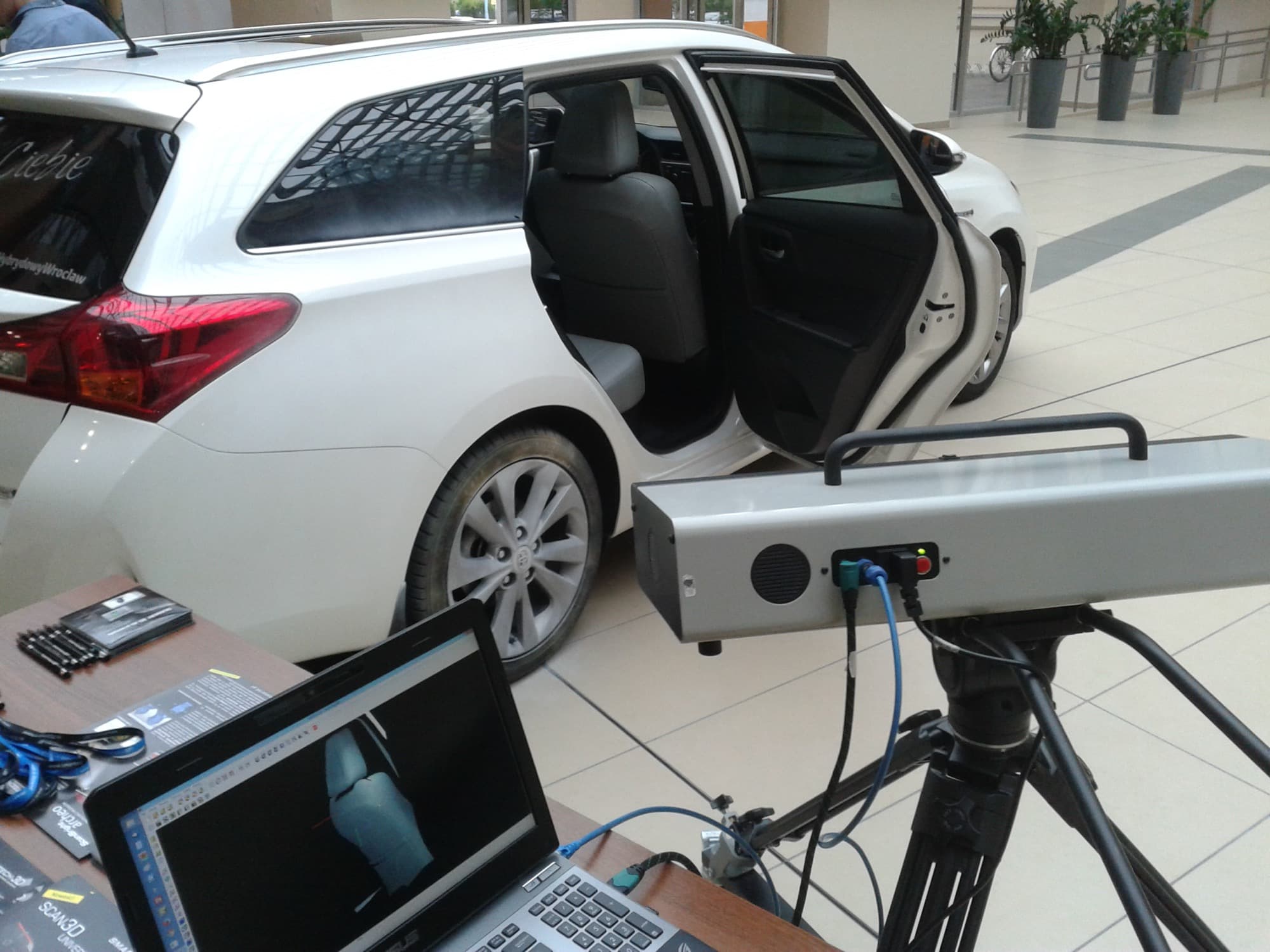
Hero photo by Deeriox via Wikimedia Commons (CC BY-SA 4.0).