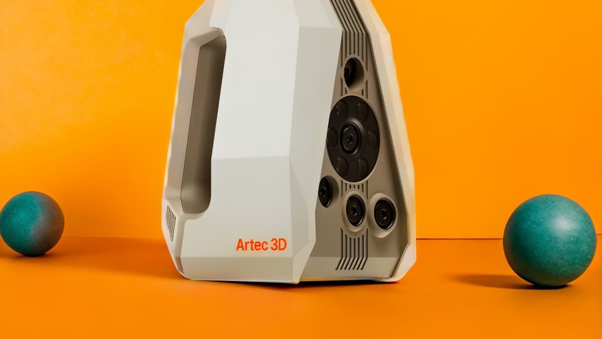
Reverse engineering a physical part into a printable 3D model requires a fundamentally different skill set than standard 3D printing. The scan is the easy part. Turning a raw point cloud into a clean, dimensionally accurate, print-ready mesh — that's where most services fall short.
This post contains affiliate links. If you purchase through these links, 3D Prototyping Hub may earn a small commission at no extra cost to you.
This post also contains Amazon affiliate links. As an Amazon Associate we earn from qualifying purchases.
This guide explains the 3D scanning and reverse engineering workflow, what separates a useful deliverable from a useless one, and how to evaluate service providers before you spend money.
What Is 3D Scanning for Reverse Engineering?
Reverse engineering via 3D scanning is the process of capturing the geometry of a physical part, processing the scan data into a usable 3D model, and either printing a direct copy or using the model as a reference for redesign.
Common use cases:
- Recreating obsolete or discontinued parts that no longer have digital files
- Creating replacement parts for machinery where no CAD files exist
- Capturing as-built geometry of legacy components for modification
- Generating a baseline 3D model for design iteration
The process has three distinct phases: scan capture, mesh processing, and model reconstruction. Most 3D scanning services only do the first one well.
Phase 1: Scan Capture — The Technology Options
Structured Light Scanning projects a pattern of light onto a part and uses cameras to triangulate surface geometry. Typical accuracy: 0.02–0.05mm. Best for small to medium parts (up to ~1 meter) that need high accuracy. Slower than photogrammetry for large parts but significantly more accurate for engineering applications.
Laser Scanning (Handheld) sweeps a laser line across a surface while cameras track the scanner position. Accuracy: 0.05–0.1mm. Flexible for large parts and complex environments. Good for medium-to-large industrial components.
CT Scanning (Computed Tomography) uses X-ray to capture both external and internal geometry. The only scanning technology that captures hidden features, internal channels, and wall thickness. Expensive but essential for parts where internal geometry matters.
Photogrammetry uses a series of photographs to reconstruct 3D geometry via software. Low cost, good for large objects, but typical accuracy is 0.1–1mm+ — insufficient for precision engineering parts. Fine for visual or architectural reference, not for mechanical replication.
For reverse engineering of mechanical parts: structured light or laser scanning. For internal features: CT. For visual reference only: photogrammetry.
Phase 2: Mesh Processing — Where Most Services Stop
A raw scan produces a point cloud: millions of unstructured data points representing the surface. Point clouds must be converted to a polygon mesh (typically STL), which requires:
- Registration — aligning multiple scan passes into one unified dataset
- Noise reduction — removing erroneous points from reflective surfaces, scan artifacts, and environmental interference
- Hole filling — closing gaps where the scanner couldn't reach (undercuts, deep cavities)
- Mesh decimation — reducing triangle count to a manageable file size without losing important geometry
A cleaned mesh is technically printable, but it is not a proper CAD model. It will print a copy of the part, including every dent, tool mark, and surface imperfection from the original. This is sufficient for some applications and insufficient for others.
Phase 3: Model Reconstruction — What Reverse Engineering Actually Means
True reverse engineering produces a parametric CAD model from the scan data — not just a mesh copy. This involves:
- Surface fitting — recognizing flat planes, cylinders, spheres, and other geometric primitives in the mesh and replacing them with clean CAD surfaces
- Dimensioning to nominal — rounding measured dimensions to standard nominal values (a 12.04mm hole becomes a 12.00mm hole based on engineering judgment)
- Feature extraction — identifying thread forms, radii, draft angles, and other engineering features from the scan and modeling them explicitly
The output is a STEP or IGES file with clean geometry, editable dimensions, and full CAD functionality — not just a mesh blob.
This phase requires a skilled CAD engineer, not just a scanner operator. It is significantly more expensive than a scan + mesh only service, and it's the deliverable most people actually need.
Evaluating a 3D Scanning Service for Reverse Engineering
Ask these questions before hiring:
-
What is your deliverable? Mesh only (STL), or parametric CAD (STEP/IGES)? If you need to modify the part or use it in an assembly, you need STEP.
-
What scanner do you use and what is the stated accuracy? Any serious service should be able to state their scanner's accuracy specification. Vague answers like "very accurate" are a red flag.
-
Have you scanned parts in this material before? Shiny metal, glass, and black rubber are notoriously difficult to scan. Experienced operators know to apply scanning spray to mitigate reflectivity. Inexperienced ones deliver point clouds full of holes.
-
What software do you use for processing? Professional mesh processing software: Geomagic, Zeiss GOM, FARO, Polyworks. Consumer/hobbyist tools: MeshLab, Meshmixer. If they can't name their software, keep looking.
-
Can you provide a sample of a previous deliverable in my industry? A scan of an automotive bracket, a medical housing, or a complex manifold tells you more about their capability than any website description.
-
What file formats do you deliver? At minimum: STL for print-only, STEP for engineering. If they only deliver proprietary formats, ask why.
Tolerances and Fit-for-Purpose
Before ordering a scan, define your end use:
- Direct print replication — a mesh is sufficient. Accuracy to ±0.2mm is acceptable for most consumer parts.
- Modification and redesign — you need a parametric STEP file. The mesh is a reference only.
- Replacement parts for precision machinery — tolerances of ±0.05mm or better are required. Only structured light or CT scanning at a qualified shop will achieve this.
- Regulatory or inspection applications — a GD&T report against nominal CAD is required, not just a mesh.
Communicate your end use to the scanning service upfront. Mismatched expectations between "scan deliverable" and "what I actually need" are the most common source of disappointed customers.
What a Qualified Service Looks Like
A capable 3D scanning service for reverse engineering will:
- Use commercial-grade structured light or laser scanning hardware (Artec, Creaform, FARO, Hexagon, Zeiss)
- Have professional mesh processing software in-house
- Offer both mesh-only and CAD reconstruction deliverables, with clear pricing for each
- Be able to state accuracy specifications and provide metrology reports
- Have experience with your part's material (metal, plastic, rubber, composite)
- Understand the difference between a scan copy and a reverse-engineered CAD model
Many providers in the 3D Prototyping Hub directory offer 3D scanning and reverse engineering services alongside their printing capabilities. Browse scanning service providers by state to find qualified shops in your area.
When Scanning Is Not the Right Approach
Not every reverse engineering project needs a scan. Before commissioning a scan:
-
Search existing databases — GrabCAD, Thingiverse, and manufacturer websites often have the part already modeled. Check before spending money on a scan.
-
Manual measurement for simple geometry — If the part is a simple extrusion, turned component, or standard weldment, a skilled CAD engineer can recreate it from calipers and measurements in 1–2 hours. No scan needed.
-
Standard hardware — Bolts, bearings, sprockets, gears, and most standard hardware have dimensional standards (DIN, ISO, ANSI) and free CAD downloads. Never scan a standard bolt.
Scanning is the right answer when the geometry is complex, freeform, or organic — and when manual measurement would take longer than the scan capture and reconstruction combined.
If you scan often enough to justify owning the hardware, a capable handheld makes reverse-engineering capture routine — see our guide to the best 3D scanners in 2026 for picks by budget and accuracy. For one-off or metrology-grade jobs, hiring a scanning service provider is almost always cheaper and more reliable than buying and learning a scanner.
Hero photo by Karina Shchukina via Unsplash.
Ready to find a 3D printing service provider?
Browse 2,000+ verified providers across the United States and submit your quote request free.
Browse Providers