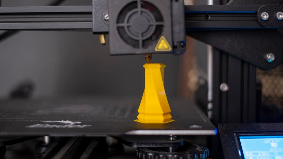
The part looks perfect. The walls are smooth, the dimensions are right, nothing failed during the print. Then you fill it, walk away, and come back to a ring of water on the bench. 3D printed parts leak for a reason that has nothing to do with the plastic being porous — an FDM wall is built from separate beads of extrusion that bond only where they were hot enough to weld to each other, which means every printed wall contains a continuous spiral seam running from the first layer to the last. Sealing a part is the job of closing that seam, and it is settings and geometry rather than luck.
This post contains affiliate links. If you purchase through these links, 3D Prototyping Hub may earn a small commission at no extra cost to you.
This post also contains Amazon affiliate links. As an Amazon Associate we earn from qualifying purchases.
Find Where It Leaks Before You Change a Setting
There are four distinct leak paths and they need four different fixes, so identify yours first. It takes ten minutes.
- Fill it with water and dye it. Food colouring makes a slow weep visible in seconds instead of half an hour. Sit the part on a dry paper towel and watch where the first spot appears.
- Or pressurise it gently. Blank one opening, blow in low-pressure air through the other, and brush soapy water over the outside. Bubbles find leaks that water takes an hour to show. Low pressure — a printed vessel is not a pressure test rig.
- Read the pattern, not the location. A single vertical line of beads is the Z seam. Beads spread evenly across a whole face are porous walls. Water arriving at the bottom first is usually the first layer or a floor that is too thin. Weeping around a fitting or a threaded boss is the join, not the wall.
| What you see |
What it is |
Where to fix it |
| One vertical line of drops |
The Z seam, where every layer starts and stops |
Slicer: seam position and extra perimeters |
| Fine weeping over a whole face |
Under-bonded or gappy walls |
Nozzle size, temperature, cooling, wall count |
| Water at the base, walls dry |
First layer or bottom solid layers |
Layer height, bottom layer count, squish |
| Drips at a boss, fitting or thread |
The joint, not the print |
Design: gasket, O-ring or insert |
The Settings That Actually Close a Wall
Watertightness is decided by how well each bead welds to the one beside and below it. Four settings control that, and most sealing failures are fixed by the first two alone.
Use a bigger nozzle. A 0.6mm nozzle lays a thicker bead that carries more heat into the layer below and cools more slowly, and thicker beads deform into each other under nozzle pressure far more reliably than 0.4mm lines do. If you print functional vessels regularly, a 0.6mm hardened steel nozzle is the single highest-yield change available, and hardened steel costs little more and survives filled filaments.
Print hotter and cool less. Layer bonding is a welding problem: the incoming bead has to melt the surface of the one below it. Move to the top of the material's temperature range, cut part cooling to 30-50% for PETG, and slow the outer walls down. Everything that makes overhangs crisp — cold air, fast walls, low temperatures — makes a part leak. The same physics in its failure mode is why prints snap along layer lines, and a part that snaps cleanly along a layer would have leaked there too.
Add perimeters and make the wall a multiple of them. Three or four perimeters, not two. More importantly, model the wall to an exact multiple of the extrusion width: a 1.7mm wall sliced at 0.6mm lines leaves a sliver the slicer cannot fill with a whole bead, and that sliver is a leak path down the whole part. Make it 1.8mm. Check what came out with calipers rather than trusting the preview.
Move the seam, don't hide it. Aligned seams stack every layer's start point into one vertical channel, which is the neatest leak path a slicer can build. Set the seam to random, or use scarf or "smart" seam placement if your slicer has it, and put it on a face that is not part of the sealed boundary where the geometry allows.
Infill is not on this list, and that is deliberate — cranking infill to 100% is the most common non-fix in this whole subject. It adds material inside a boundary that is already leaking, and the extra shrinkage stress pulls at the perimeters. Three perimeters at 20% beats two perimeters at 100% every time.
One thing to rule out before any of it: wet filament. PETG and nylon absorb moisture from room air over weeks, and a wet spool steams in the melt zone and leaves microvoids straight through the wall. A few hours in a heated dryer box is the cheapest way to eliminate the variable, and the same porosity shows up as under-extrusion on parts that are not vessels at all.
Material Decides How Hard the Rest Has to Work
| Material |
Sealing behaviour |
The catch |
| PETG |
Strong layer bonding, ductile, wide melt window |
Needs reduced cooling; absorbs moisture on the shelf |
| ABS / ASA |
Seals well and can be vapour-smoothed to a continuous skin |
Needs an enclosure; warps and splits without one |
| PLA |
Adequate for cold water, short term |
Creeps under sustained load, softens in warm conditions |
| TPU |
Excellent as a gasket, poor as a vessel |
Hard to print thin-walled and dimensionally exact |
| Nylon |
Prints strong parts |
Absorbs water into the polymer and swells — a poor barrier |
PETG is the default for a reason and our PETG buyer's guide covers the brand-level differences; generic 1.75mm PETG is entirely adequate for sealing work. If the vessel lives outdoors or gets warm, ASA is UV-stable and holds its shape, but it brings a hardware requirement with it: an actively heated chamber, not a box with a lid. That is a machine specification rather than an accessory, and the chamber temperature figure is the one to read — QIDI's enclosed machines publish it, and our guide to enclosed printers covers what a chamber does and does not do. On the PETG side there is no chamber requirement at all, and the useful specifications are a hotend that holds temperature under high flow and a 0.6mm nozzle listed for the model — ELEGOO's US store lists both alongside the machines.
Design the Seal Instead of Fighting the Printer
The parts that seal reliably are the ones designed so the seam is not doing the sealing.
- Orient the part so the pressure boundary is not a layer plane. A cylinder printed upright has its wall in the strong direction and its floor joint in the weak one. Printing the same cylinder on its side puts every layer line across the pressure boundary. Orientation changes the answer more than any slicer setting.
- Fillet internal corners. A sharp internal corner concentrates stress exactly where the perimeters meet, and it is where a vessel splits first.
- Never seal with printed threads. Threads clamp the load directly into the layer lines you are trying to close, and printed threads strip and deform anyway — the full version is in why printed threads strip. Use heat-set inserts and a bolted flange instead.
- Put a gasket between rigid faces. Two printed faces bolted together will not seal, because neither is flat at the scale that matters. A groove sized for a standard silicone O-ring, compressed about a quarter of its cross-section, removes surface finish from the equation. A printed TPU gasket does the same job when the geometry is not a standard ring.
- Thicken the floor. Bottom layers take the hydrostatic load and get the roughest treatment from the build plate. Five or six solid bottom layers, not three.
Coating: The Patch, and What It Cannot Do
When reprinting is expensive or the part is already in service, a coating is the pragmatic answer. Brush a thin coat of two-part epoxy over the wetted surface, let it self-level, and it bridges the layer seams. For ABS only, acetone vapour smoothing fuses the outer skin into a continuous surface, which is a real seal rather than a film over one.
Two honest limits. A coating is a surface film, so any flex in the part cracks it and the leak returns in exactly the same place — it does not compensate for walls that are too thin. And it seals only what it touches: coating the outside of a vessel whose water sits inside leaves the wall soaking and the seam working. Coat the wet side.
When the Part Should Not Be Printed on a Desktop at All
Three cases are worth being blunt about, because getting them wrong costs more than a reprint.
Anything pressurised. Layer adhesion is the weak axis, and pressure concentrates exactly at the seam and the corners. A desktop part is good for low single-digit psi held briefly, and compressed air is worse than water because it stores energy and fails all at once.
Anything food or drink contact. The layer crevices hold residue and cannot be properly sanitised, most nozzles are brass, and "food-safe filament" does not survive contact with an uncertified machine. Print the prototype, then have the real one made.
Anything that has to seal for years. Thermal cycling, UV and creep all work on a printed seam, and a part that passed a bench test in May can weep in August — the same mechanism as prints deforming in a hot car.
In all three, the move is to switch process rather than to keep tuning. SLA and SLS parts have no layer seam in the same sense, machined polymer is isotropic, and cast or moulded parts are a continuous solid. The providers in our directory quote one-off sealed housings, tanks and manifolds in those processes, usually in a few days, and for a part that has to hold liquid in front of a customer that is a better answer than a fourth print with the cooling fan turned down a bit further.
Hero photograph by Osman Talha Dikyar via Unsplash.
Ready to find a 3D printing service provider?
Browse 2,000+ verified providers across the United States and submit your quote request free.
Browse Providers