The half-size test print was fine. You opened the same file, typed 200% into the scale box, printed it overnight, and it cracked the first time it took load — or lifted a corner off the bed at hour six and ruined eleven hours of plastic. 3D printed parts fail when you scale them up because the model is the only thing that scaled. The wall thickness, the layer height, the bridging distance, the clearances and the strength of the bond between layers all stayed exactly where they were.
This post contains affiliate links. If you purchase through these links, 3D Prototyping Hub may earn a small commission at no extra cost to you.
This post also contains Amazon affiliate links. As an Amazon Associate we earn from qualifying purchases.
Read the Failure First
Six different mechanisms are hiding behind "it worked small and failed big", and they want opposite fixes.
| What happened |
What it is |
Where to start |
| Snapped under a load the small one held |
Mass went up 8x, cross-section only 4x |
Thicken the structure, not the infill |
| Flexes or sags where the small one felt rigid |
Same 0.8mm shell on a part twice the size |
Wall count, or wall thickness in mm |
| A corner lifted, or a seam split mid-print |
Contraction is proportional to length |
Enclosure, material, bed strategy |
| Broke cleanly along one layer |
The weak plane is unchanged; the leverage is not |
Re-orient, or split and bolt |
| Ceilings sagged, bridges drooped |
Spans doubled; bridging ability did not |
Re-model the span, or support it |
| Screws spin, press fits are loose |
The holes and clearances scaled too |
Model hardware at fixed size |
The useful first question is whether it failed while printing or in service. A print-time failure is nearly always warping, spans or time at risk. A service failure is nearly always the shell.
The Part Got Eight Times Heavier and Only Four Times Stronger
Scale a part 2x in every direction and its volume — and therefore its mass — goes up by 8. The cross-section that has to carry that mass goes up by only 4. Self-weight stress doubles. At 3x it triples.
That is the square-cube law, and the honest version of it has a caveat worth stating: if the load stays the same, a bigger part is genuinely stronger. A doubled bracket holding the same 2kg shelf has four times the cross-section and is in much better shape. The trap is that people rarely scale a part on its own. The whole job scales — the bigger bracket holds a bigger shelf, the bigger arm swings a bigger mass, the bigger housing contains heavier contents — and once the load scales with the part, the part is losing.
So before changing any setting: did the load scale too? If it did, you are not reprinting a model, you are designing a different part, and the prototype that passed tells you nothing about the one you need.
Your Walls Did Not Scale
This is the mechanism that catches the most people, because it is invisible in the slicer preview.
Perimeter count is a slicer setting, not a property of the model. Two walls at 0.4mm is 0.8mm of shell whether the part is 40mm across or 400mm. When a part bends, the shell does nearly all the work — it is the flange of an I-beam, and the infill is only the web holding the flanges apart. Double the model with the same two perimeters and you have built something with a proportionally thinner skin than the thing you tested.
The fix is to make the shell scale deliberately:
- Set wall thickness in millimetres, not in number of walls. If 0.8mm of shell worked at 1x, specify 1.6mm at 2x and let the slicer decide how many passes that takes.
- Add walls before you add infill. Perimeters sit at the outside surface, where bending stress is highest. Infill sits near the middle, where stress is near zero. Going from two walls to four costs a little time and buys real stiffness; going from 20% to 40% infill costs a lot of both time and plastic for much less.
- Match the top and bottom solid layers. They are the other two flanges, and the same logic applies.
- Watch the parts that are still thin. A 1.5mm rib that was proportionate on the test print is a 3mm rib on the scaled one — but a 1.5mm wall thickness setting is still 1.5mm, so any feature you left at the slicer's minimum is now relatively weaker than everything around it.
If the part is flexing rather than breaking, this section is almost certainly your answer. The same shell-versus-infill reasoning is why printed brackets sag under a load they survived on day one.
Warping Scales With Length, and Bed Adhesion Does Not Keep Up
Thermal contraction is proportional to the dimension. ABS shrinks on the order of 0.8% as it cools from print temperature: a 100mm part pulls in about 0.8mm, and the same part at 300mm pulls in about 2.4mm. PLA is roughly a third of that, which is why PLA gets away with a lot at small sizes and much less at large ones.
The bed holds the middle of the part. All that accumulated contraction has to go somewhere, and it goes to the corners, which is where it peels. A footprint that was comfortably inside the adhesion budget at 100mm can be well outside it at 300mm with nothing else changed.
What actually helps, in order:
- Still, warm air around the whole part. An enclosure over an open machine stops the draught that cools one side of a large part faster than the other. This matters far more at 300mm than at 100mm.
- A lower-shrinkage material if the application allows it — the general warping mechanics are covered in why 3D prints warp, and they get worse with every millimetre of footprint.
- Geometry changes at the corners. Rounding sharp corners spreads the peel force instead of concentrating it at a point.
If the material the part now needs is ABS, ASA or a filled engineering filament, an open bed-slinger in a cool room is the wrong tool rather than a badly tuned one. That is the case for an enclosed machine with a heated chamber — QIDI's enclosed, larger-volume printer line publishes chamber and nozzle temperatures per model, and Anycubic's US store is the other direct route worth checking on build volume. Our large-format printer guide covers how to read those numbers against a specific part.
Bridges and Overhangs Got Twice as Long
Overhang angle is scale-invariant — a 45° face is 45° at any size. Span is not. A 20mm bridge across the top of a box becomes a 40mm bridge, and bridging quality falls off sharply with distance because the extrusion has further to go before it is supported by anything.
So a scaled part often prints with sagging ceilings, drooping horizontal holes and a rough underside on features that came out crisp at half the size. Two real fixes: support the span, or re-model it — chamfer the top of a hole into a teardrop, add an internal rib under a wide ceiling, or split the part so the span prints vertically. Adding supports under a 40mm bridge works, but it is the answer that costs the most surface finish.
The Holes Scaled Too, and Hardware Did Not
Uniform scaling applies to every dimension, including the ones that were matched to a real object:
- A 3.2mm clearance hole for an M3 screw becomes 6.4mm. The screw is still M3.
- A 0.2mm press-fit clearance becomes 0.4mm, so the fit that was snug is now loose.
- A snap-fit arm designed to deflect a fixed distance now has to deflect twice as far, through a beam that is twice as stiff in section.
- A bearing seat, a slot for a standard extrusion, a cutout for a connector — all now wrong by exactly the scale factor.
Anything that touches a bought part must be re-cut at its true size after scaling. On a large part the cleanest way to do that is often not to model threads at all: bore a plain hole and press in a heat-set threaded insert, which gives a steel thread that can be torqued properly and does not care what the scale factor was. Printed threads at large sizes have their own failure mode, covered in why 3D printed threads strip.
Print It in Sections, and Design the Joint
Past a certain size, one piece stops being the goal. An eight-fold increase in volume is roughly an eight-fold increase in print time for an infill-dominated part, which turns a 6-hour print into a 2-day one — two days in which a clog, a power blip or a damp spool costs you the whole thing.
Splitting is not a compromise if the joint is designed rather than improvised:
- Flat, large mating faces. Surface area is the whole budget for a bonded joint.
- Alignment features, not alignment by eye. Printed dowel pins, a shallow tongue and groove, or a pair of holes for steel rod.
- Put the seam where the stress is not — the one real advantage of splitting is that you choose the location of the weak plane, which is more than the layer lines will ever let you do.
- Epoxy for structure. Two-part epoxy fills the texture left by layer lines and stays tough; cyanoacrylate sets in seconds and is brittle. Most failed bonds are a materials choice rather than a technique problem, which is the subject of why glued 3D prints come apart.
- Or bolt it. Inserts plus machine screws make a joint you can inspect, torque and disassemble.
While you are reprinting anyway, change the nozzle. A 0.6mm or 0.8mm nozzle lays down a much larger cross-section per pass, which cuts print time hard and produces thicker extrusions that fuse to each other better than thin ones do. You lose fine detail, which a large structural part usually was not relying on. If the material also needs to be stiffer, a carbon-fibre nylon buys real rigidity — and needs a hardened nozzle and a dry spool to print at all.
When the Scaled Part Is Not a Desktop Job
Large parts amplify every weakness of a hobby machine simultaneously: frame flex over a longer travel, bed flatness across the full plate, chamber temperature, and many more hours during which something can go wrong. There is a size past which the honest answer is a different machine or a different supplier.
Send it out when the part has to be dimensionally correct across its whole length, when it carries a load you do not want to test by hand twice, or when it simply does not fit. A shop with a large-format machine prints it in one piece on equipment designed for the envelope, and the trade-offs between processes at size are set out in large-format 3D printing services. You can browse providers by location and process and have two or three quotes back before a four-day print would have finished.
Fix It in This Order
- Ask whether the load scaled too. If it did, this is a design change, not a reprint.
- Scale the shell with the part. Set wall thickness in millimetres, add walls before infill, match the solid layers.
- Re-cut every hardware feature — screw holes, press fits, bearing seats, snap arms — back to its true fixed size.
- Deal with the footprint: enclosure, lower-shrinkage material, rounded corners.
- Change the nozzle to 0.6mm or 0.8mm and the layer height with it, so the print is hours rather than days.
- Split it and design the joint when one piece stops being realistic, or send it out when the envelope and the tolerance both exceed what the machine can hold.
Most scaled-part failures are step two wearing a disguise. The ones that survive a thicker shell are telling you the job outgrew the printer, not the settings.
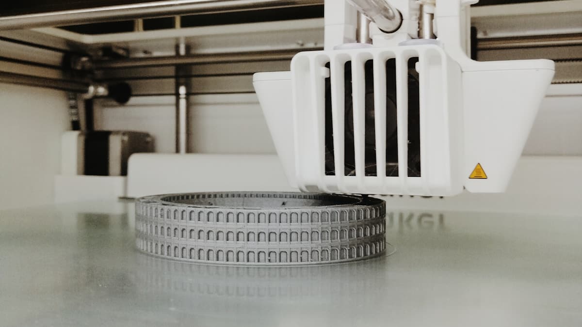
Hero photograph by Andrea G on Unsplash.
Ready to find a 3D printing service provider?
Browse 2,000+ verified providers across the United States and submit your quote request free.
Browse Providers